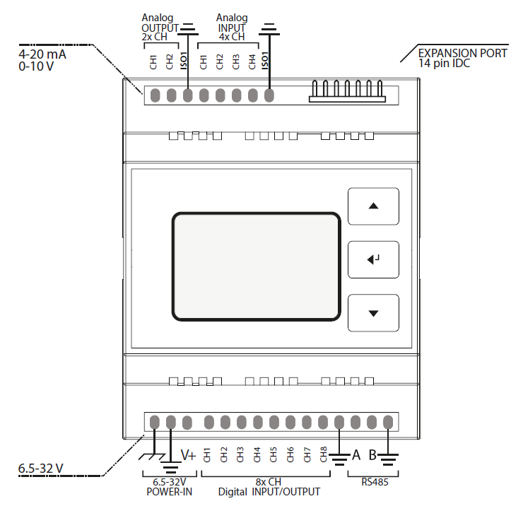
Typical Wiring Variants
|
|
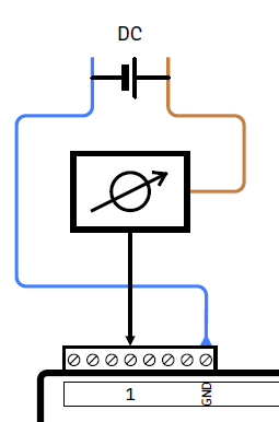
Connecting an analog sensor (AIN field) or analog actuator (AOUT field) in series
Typical application: |
||||||||
|
|
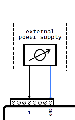
Connecting an analog sensor (AIN field) or analog actuator (AOUT field), using an external power
|
||||||||
|
|
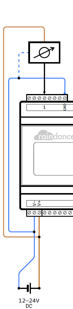
Connecting an analog sensor (AIN field) or analog actuator (AOUT field), supplied by the same PSU.
Example:
Hinweis:
Hinweis: |
||||||||
|
|
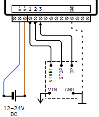
Typical connection of a control unit using a pulsed signal (active high, pulse width configurable) for Start (CH1) and Stop (CH2).
Feedback of the operational state via permanent signal (active high) via input CH3.
Create a common ground reference when using a separate power supply by connecting the GND terminal of the digital field.
|
||||||||
|
|
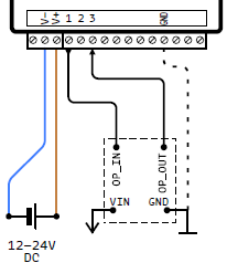
Typical connection of a control unit using a permanent signal (optionally configurable) on output
|
||||||||
|
|
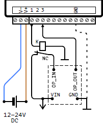
Example adaptation to a control unit using a permanent signal (active low) via a NC switch at CH1.
|
||||||||
|
|
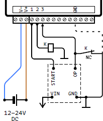
Example adaptation for driving an NC switch to pull an active output low in order to stop the connected control.
The active output may be used as a feedback of the operational state.
Create a common ground reference when using a separate power supply by connecting the GND terminal of the digital field.
|
||||||||
|
|
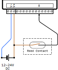
Typical connection of a counter at input CH8. The depicted example uses a simple Reed contact.
Alternatively, any kind of impulse generator can be connected to CH8 (input active high).
The impulse frequency has to be selected according to the desired application. |
No Comments