# Technical Data

- [![image.png](https://help.raindancer.com/uploads/images/gallery/2024-03/scaled-1680-/9U0image.png)](https://help.raindancer.com/uploads/images/gallery/2024-03/9U0image.png)ATSAMD21G18 Microcontroller
- 128x64 px LCD Screen with Backlight
- Membrane 3 Button Panel
- Ethernet Module (mandatory)  
    M2M 3G/LTE Router optionally available
- Standard Input Voltage: 12V / 24V DC  
    permissible range: 8–28V DC  
    12V, 24V PSU optionally available
- DIN-Rail mountable
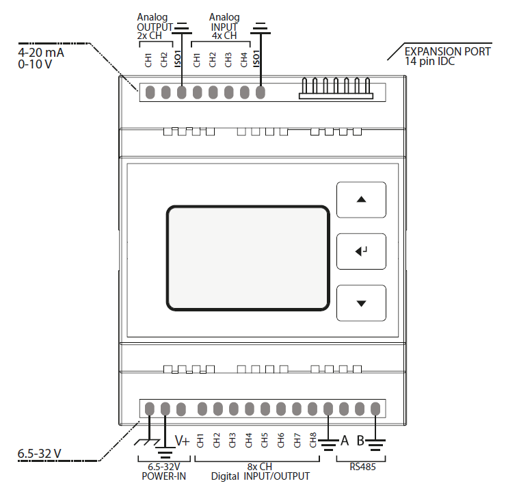
- 4 Analog Input Channels
- 2 Analog Output Channels
- Levels: 4–20mA / 0–10V
- Fully isolated from MCU and Digital Side (1kV isolation)
- 8 Digital I/O Channels
- Digital Input Voltage Range: 0–28V  
    input channels internally driven LOW
- Digital Output Vortage Range: 8–28V (tied to VIN)
- Digital I/O Levels: LOW ≤ 3V, HIGH ≥ 11V  
    I/O Logic is active high
- Max. Output Current per Pin: 2.6A  
    (short circuit, over-current, over-temp. protected)
- Max. Total Output Current: 6.5A (omni block fused)
- Fully isolated from MCU and Analog Side (1kV isolation)
- Isolated Half Duplex RS-485 Transceiver

#### Important Notes

To properly operate the Raindancer Beacon, it has to be connected to an adequate power supply via the POWER-IN field (12/24V DC is recommended). The USB port on the front casing is not suitable.  
When a single power supply is used to power both, Raindancer Beacon and peripherals, the GND lines should be tied together.

<p class="callout danger">Power down all systems (Raindancer Beacon, sensors/actuators) before connecting to the Raindancer Beacon via USB, internal components may irreparably take damage otherwise!</p>

#### Analog Field Section

- Analog Pins can be individually configured, according to the requirements of the devices to be connected: 0-10V or 4-20mA. By default, all Analog Pins are preconfigured to 4-20mA. An alternate configurations can be set using the web-portal.

Pin Assignment and Value Ranges when Used as Pump Control Unit:

- The value ranges can be individually adjusted using the web-portal.

<table border="1" id="bkmrk-a-out-belegung-werte" style="border-collapse: collapse; width: 100%; height: 89.3907px;"><colgroup><col style="width: 9.42392%;"></col><col style="width: 57.3252%;"></col><col style="width: 33.3745%;"></col></colgroup><thead><tr style="height: 29.7969px;"><td style="height: 29.7969px;">A OUT</td><td style="height: 29.7969px;">Assignment</td><td style="height: 29.7969px;">Default Range</td></tr></thead><tbody><tr style="height: 29.7969px;"><td style="height: 29.7969px;">CH 1</td><td style="height: 29.7969px;">Target / Min. Pressure</td><td style="height: 29.7969px;">0 – 16 bar</td></tr><tr style="height: 29.7969px;"><td style="height: 29.7969px;">CH 2</td><td style="height: 29.7969px;">Manually Set Pressure</td><td style="height: 29.7969px;">0 – 16 bar</td></tr></tbody></table>

<table border="1" id="bkmrk-a-in-belegung-werteb" style="border-collapse: collapse; width: 100%; height: 148.984px;"><thead><tr style="height: 29.7969px;"><td style="height: 29.7969px; width: 9.67083%;">A IN</td><td style="height: 29.7969px; width: 57.0782%;">Assignment</td><td style="height: 29.7969px; width: 33.3745%;">Default Range</td></tr></thead><tbody><tr style="height: 29.7969px;"><td style="height: 29.7969px; width: 9.67083%;">CH 1</td><td style="height: 29.7969px; width: 57.0782%;">Current Pressure</td><td style="height: 29.7969px; width: 33.3745%;">0 – 16 bar</td></tr><tr style="height: 29.7969px;"><td style="height: 29.7969px; width: 9.67083%;">CH 2</td><td style="height: 29.7969px; width: 57.0782%;">Current Power</td><td style="height: 29.7969px; width: 33.3745%;">0 – 100 kW</td></tr><tr style="height: 29.7969px;"><td style="width: 9.67083%; height: 29.7969px;">CH 3</td><td style="width: 57.0782%; height: 29.7969px;">Current Flow</td><td style="width: 33.3745%; height: 29.7969px;">0 – 100 m³/h</td></tr><tr style="height: 29.7969px;"><td style="width: 9.67083%; height: 29.7969px;">CH 4</td><td style="width: 57.0782%; height: 29.7969px;">Current Speed</td><td style="width: 33.3745%; height: 29.7969px;">0 – 3.600 rpm</td></tr></tbody></table>

#### Digital Field Section

- Output can be configured as a permanent or pulsed signal (125ms – 256s).   
    Signal configuration can be adjusted using the web-portal.
- Pulse counter (using level raise/fall, max. ca. 60Hz), e.g. for water meters on Digital Channel 8.
- Please note that floating/pulsing input voltages may be transmitted as highly fluctuating input signals, triggering associated actions (e.g. error notification).

Default Pin Assignment and Value Ranges When Used as Pump Control Unit:

<table border="1" id="bkmrk-d-ch-belegung-signal" style="border-collapse: collapse; width: 100%; height: 268.172px;"><thead><tr style="height: 29.7969px;"><td style="height: 29.7969px; width: 9.64153%;">D CH</td><td style="height: 29.7969px; width: 28.5538%;">Assignment</td><td style="width: 28.5538%; height: 29.7969px;">Signal</td><td style="height: 29.7969px; width: 33.3745%;">Interpret.</td></tr></thead><tbody><tr style="height: 29.7969px;"><td style="height: 29.7969px;">**1 (OUT)**</td><td style="height: 29.7969px; width: 28.5538%;">Control ON</td><td style="width: 28.5538%; height: 29.7969px;">Pulse, 125ms</td><td style="height: 29.7969px; width: 33.3745%;">ON</td></tr><tr style="height: 29.7969px;"><td style="height: 29.7969px;">**2 (OUT)**</td><td style="height: 29.7969px; width: 28.5538%;">Control OFF</td><td style="width: 28.5538%; height: 29.7969px;">Pulse, 125ms</td><td style="height: 29.7969px; width: 33.3745%;">OFF</td></tr><tr style="height: 29.7969px;"><td style="height: 29.7969px;">**3 (IN)**</td><td style="width: 28.5538%; height: 29.7969px;">Confirmation</td><td style="width: 28.5538%; height: 29.7969px;">Permanent</td><td style="width: 33.3745%; height: 29.7969px;">ON/ OFF</td></tr><tr style="height: 29.7969px;"><td style="height: 29.7969px;">**4 (IN)**</td><td style="width: 28.5538%; height: 29.7969px;">Error Code 1</td><td style="width: 28.5538%; height: 29.7969px;">Permanent</td><td style="width: 33.3745%; height: 29.7969px;">ON/ OFF</td></tr><tr style="height: 29.7969px;"><td style="height: 29.7969px;">**5 (IN)**</td><td style="width: 28.5538%; height: 29.7969px;">Error Code 2</td><td style="width: 28.5538%; height: 29.7969px;">Permanent</td><td style="width: 33.3745%; height: 29.7969px;">ON/ OFF</td></tr><tr style="height: 29.7969px;"><td style="height: 29.7969px;">**6 (IN)**</td><td style="width: 28.5538%; height: 29.7969px;">Error Code 3</td><td style="width: 28.5538%; height: 29.7969px;">Permanent</td><td style="width: 33.3745%; height: 29.7969px;">ON/ OFF</td></tr><tr style="height: 29.7969px;"><td style="height: 29.7969px;">**7 (OUT)**</td><td style="width: 28.5538%; height: 29.7969px;">Reset Error</td><td style="width: 28.5538%; height: 29.7969px;">Pulse, 2s</td><td style="width: 33.3745%; height: 29.7969px;">  
</td></tr><tr style="height: 29.7969px;"><td style="height: 29.7969px;">**8 (IN)**</td><td style="width: 28.5538%; height: 29.7969px;">Counter</td><td style="width: 28.5538%; height: 29.7969px;">Pulse</td><td style="width: 33.3745%; height: 29.7969px;">  
</td></tr></tbody></table>

#### Error Codes

- By combining the three main Error Codes using Digital Channels 4 – 6, four additional states, up to a total of 7, can be transmitted.
- • The textual interpretations of the Error Codes can be customized individually using the web-portal.

Default Error Codes Used by Pump Control/Monitoring:

<table border="1" id="bkmrk-code-1%28ch-4%29-code-2%28" style="border-collapse: collapse; width: 100%; height: 284.969px;"><thead><tr style="height: 46.5938px;"><td class="align-center" style="height: 46.5938px; width: 8.77627%;">Code 1  
(CH 4)</td><td class="align-center" style="height: 46.5938px; width: 8.77627%;">Code 2  
(CH 5)</td><td class="align-center" style="height: 46.5938px; width: 8.77627%;">Code 3  
(CH 6)</td><td style="height: 46.5938px; width: 73.6712%;">Interpretation</td></tr></thead><tbody><tr style="height: 29.7969px;"><td class="align-center" style="height: 29.7969px; width: 8.77627%;"><span style="color: rgb(149, 165, 166);">0</span></td><td class="align-center" style="height: 29.7969px; width: 8.77627%;"><span style="color: rgb(149, 165, 166);">0</span></td><td class="align-center" style="height: 29.7969px; width: 8.77627%;"><span style="color: rgb(149, 165, 166);">0</span></td><td style="width: 73.6712%; height: 29.7969px;"><span style="color: rgb(149, 165, 166);">no malfunction</span></td></tr><tr style="height: 29.7969px;"><td class="align-center" style="height: 29.7969px; width: 8.77627%;"><span style="color: rgb(186, 55, 42);">**1**</span></td><td class="align-center" style="height: 29.7969px; width: 8.77627%;"><span style="color: rgb(186, 55, 42);">0</span></td><td class="align-center" style="height: 29.7969px; width: 8.77627%;"><span style="color: rgb(186, 55, 42);">0</span></td><td style="height: 29.7969px; width: 73.6712%;"><span style="color: rgb(186, 55, 42);">Malfunction - Pressure, generic.</span></td></tr><tr style="height: 29.7969px;"><td class="align-center" style="height: 29.7969px; width: 8.77627%;"><span style="color: rgb(186, 55, 42);">0</span></td><td class="align-center" style="height: 29.7969px; width: 8.77627%;"><span style="color: rgb(186, 55, 42);">**1**</span></td><td class="align-center" style="height: 29.7969px; width: 8.77627%;"><span style="color: rgb(186, 55, 42);">0</span></td><td style="height: 29.7969px; width: 73.6712%;"><span style="color: rgb(186, 55, 42);">Malfunction - Motor Temperature</span></td></tr><tr style="height: 29.7969px;"><td class="align-center" style="height: 29.7969px; width: 8.77627%;"><span style="color: rgb(186, 55, 42);">0</span></td><td class="align-center" style="height: 29.7969px; width: 8.77627%;"><span style="color: rgb(186, 55, 42);">0</span></td><td class="align-center" style="height: 29.7969px; width: 8.77627%;"><span style="color: rgb(186, 55, 42);">**1**</span></td><td style="width: 73.6712%; height: 29.7969px;"><span style="color: rgb(186, 55, 42);">Malfunction - Frequency Inverter / Pump</span></td></tr><tr style="height: 29.7969px;"><td class="align-center" style="height: 29.7969px; width: 8.77627%;">**1**</td><td class="align-center" style="height: 29.7969px; width: 8.77627%;">**1**</td><td class="align-center" style="height: 29.7969px; width: 8.77627%;">0</td><td style="width: 73.6712%; height: 29.7969px;">Malfunction - Low Pressure</td></tr><tr style="height: 29.7969px;"><td class="align-center" style="height: 29.7969px; width: 8.77627%;">**1**</td><td class="align-center" style="height: 29.7969px; width: 8.77627%;">0</td><td class="align-center" style="height: 29.7969px; width: 8.77627%;">**1**</td><td style="width: 73.6712%; height: 29.7969px;">Malfunction - Excess Pressure</td></tr><tr style="height: 29.7969px;"><td class="align-center" style="height: 29.7969px; width: 8.77627%;"><span style="color: rgb(230, 126, 35);">0</span></td><td class="align-center" style="height: 29.7969px; width: 8.77627%;"><span style="color: rgb(230, 126, 35);">**1**</span></td><td class="align-center" style="height: 29.7969px; width: 8.77627%;"><span style="color: rgb(230, 126, 35);">**1**</span></td><td style="width: 73.6712%; height: 29.7969px;"><span style="color: rgb(230, 126, 35);">Restart after Interruption of Power Supply</span></td></tr><tr style="height: 29.7969px;"><td class="align-center" style="height: 29.7969px; width: 8.77627%;"><span style="color: rgb(230, 126, 35);">**1**</span></td><td class="align-center" style="height: 29.7969px; width: 8.77627%;"><span style="color: rgb(230, 126, 35);">**1**</span></td><td class="align-center" style="height: 29.7969px; width: 8.77627%;"><span style="color: rgb(230, 126, 35);">**1**</span></td><td style="width: 73.6712%; height: 29.7969px;"><span style="color: rgb(230, 126, 35);">Remote Control Disabled</span></td></tr></tbody></table>