Instructions & How-To's
Here you will find the necessary information on the installation and basic settings of the Raindancer product range.
You can find a first introduction to the use of Raindancer under: Getting started with Raindancer
If you need help with the mounting of your Raindancer products, please take a look at the respective mounting instructions.
- Getting started with Raindancer
- Settings and Configurations
- Create Users and Manage Rights
- Setup Notifications
- Create a Well
- Add Fields and Areas
- Field Import
- Event areas - Getting started
- Event Areas and their Actions
- Create a Run
- Auto Speed - The cruise control for irrigation
- The Master Data - Crops and Soils
- Plan Future Operations
- Units - Metric or Imperial
- Irrigatior Control - Remote control of irrigation
- Raindancer GPS Modul
- Installing the GPS module correctly
- Reset the Module
- Maintaining and Cleaning the Solar Modules
- Storage in the Winter
- Using the Raindancer Power Supplies
- The Sector Control
- Install Sector Control correctly
- Initial start-up of the sector control
- Overhang
- Before irrigation - Checklist
- Manual Sector Control
- Transport the Sector Control
- Choosing The Perfect Angle
- The Effects of Wind
- Variable Rate Irrigation - Save Water
- Water Distribution with Sector Control at the Start and Finish
- Setup Sector Control with a boom on a Fasterholt
- The Raindancer Beacon
- The Pump in Raindancer
- Technical Data
- Initial start-up of the M2M router
- Typical Wiring Variants
- Calibration of Analogue Inputs and Outputs
- Operation Mode »Mirror Image«
- Troubleshooting in Raindancer
- Replace motorbox base plate assembly
- Install the Motor Box Correctly
- Troubleshooting the Beacon
- Remove the Motor Box Gasket
- WhatsApp Notifications are not Working.
- Troubleshooting the Sector Control
- FAQ - Frequently asked Questions
- Extended Functions of Raindancer
- Irrigation Machine - Take Control, Remotely
- Integrate third-party weather sensor data into Raindancer
- Linking Raindancer with the Pessl API
- Connect Raindancer to the Weenat-API
Getting started with Raindancer
Congratulations on your decision to work with Raindancer.
Thank you for your trust and welcome to the Raindancer cosmos.
Before you can get started and view all your irrigations in one app, there are a few small things you need to set up first.
Login credentials
This guide assumes that you have already received login credentials from your dealer or the raindancer team.
This manual gives you a guide on what to do to get started with the system in an easy way. This is really just about the bare minimum of configuration.
For a deeper insight, please follow the detailed technical documentation (coming soon) or the related pages at the bottom of this page.
Playlist bei Youtube:
https://youtube.com/playlist?list=PL8USp-bvp0udx3N1XL1w0uJ8ViMG4LuXF&si=t_3CyoPwKR6hT5M3
(Subtitles in English are available)
Users and Access
Your Raindancer is always delivered with an "Administrator" user and a service user.
Login credentials
You will receive the access data in a separate e-mail from the Raindancer team.
This also means that you already have a user in the system with which you can start working. But it is recommended to create individual users for each of your employees and to store personal data (name, first name, telephone number) for the administrator.
The following user data are required:
- First Name\Last Name
- Telephone Number or E-Mail OPTIONAL
If your user is not supposed to receive any notifications, you do not need to fill in this field.
Otherwise, please select the type of notifications, either SMS or WhatsApp (or both). - Turn on Notifications
For new users, all notifications are switched off by default.
For more information on notifications, see Set Notifications
If you want to create more users or are looking for further information on the subject of users, you can follow the instructions "Adding Users And Managing Permissions"
Permissions
By default, a new user only has the permission to use the app.
If you want a different permission for your new user, you can change this in the Group Memberships tab and assign more permissions.
Create Irrigators
If not already done by the Raindancer team, you now need to create the irrigation machine(s) in the portal.
Usually you should see a list of all serial numbers of the Raindancer GPS modules that have been assigned to you under Irrigators.
The irrigators that have already been created should of course be renamed so that they correspond to the machine on which you have mounted the Raindancer GPS module.
A combination of a continuous number, the brand and the length has been proven to be effective.
Mounting and installation
First, please make sure that your Raindancer is mounted correctly.
If you are not sure, we have a separate guide on this subject here: Installing the GPS module correctly
If a raindancer module does not appear in the list, you can also create a new irrigator.
Click on Irrigators → New Irrigator to add a new irrigation machine to your system.
Enter an irrigator name and select the type of irrigator in the selection box.
You can then select the GPS device. This is the serial number of your Raindancer.
To make sure that the system operates properly, it is advisable to set the following parameters.
- Working Width
- Min. Pressure
- Max. Pressure
- ø Nozzle
CAUTION Flow rate only for booms and linear, pivot irrigation machines
SELF-PROPELLED Please note the setting of the setup method under Setup and Controls (central) → Setup method
Essential
These parameters are essential for the most functions that your Raindancer system provides for you..
Control
OPTIONAL
If you want to control your irrigation machine via the Raindancer system, you must enter 2 additional fields.
These fields must be filled in on the Setup and Controls tab.
- Control type
- Phone No.
These fields are necessary to establish communication between your irrigation machine and the raindancer system.
Settings on the Machine
Usually a telephone number must be entered in your irrigation computer to which responses will be sent.
|
Raindancer phone number |
|---|
| +3197014444993 |
For the use of AutoSpeed read more at AutoSpeed
Sector Control
OPTIONAL
If you have decided to operate your irrigation system with sector control, we can only congratulate you on your great decision and ask you to use "The Sector Control" for further instructions.
Fields
It is necessary to add your fields to the system for almost all functions offered by the raindancer system.
Import Field Data
You generally have the option of importing your field data from external sources. This way you do not have to start from scratch.
You need shp or kml files for the import
Wells
Wells are primarily used for reporting at the end of the season.
It is advisable to enter the wells before the start of irrigation season.
To enter your wells into the system, follow these instructions: Create a Well
Fields
You can manage the fields you want to use with the Raindancer under Fields.
In this overview you can see all your registered fields, and you also have the option of adding new fields yourself.
Field Import
RECOMMENDED
To do this, you typically need an export from your other agricultural applications. All the necessary data is normally stored there.
For a more detailed explanation, follow these instructions Import Fields.
Draw in Fields
If you do not have the possibility to integrate your field data into the raindancer system with the help of the import function, you also have the possibility to enter the field data manually.
As with the manual entry, follow these instructions: Fields
Runs
For the handling of irrigation runs, it is best to continue reading at this point Working With Permanent Runs
Self-driving Irrigators with sector control
Due to the possibility of driving around curves, it is recommended to create runs in advance for self-driving irrigation machines. Otherwise, the sector control would react with delay on curves.
Help
If you have problems with these steps or the settings do not fit your application, please do not hesitate to contact your dealer.
You can find all contact details at https://www.raindancer.com/contact
Settings and Configurations
This section is constantly being updated and expanded to provide as many answers as possible to common questions and useful information.
If you have not found what you were looking for in this section, please let us know which topic you were missing and we will add your suggestions to our knowledge database.
Für Feedback oder Anregungen treten Sie gern mit uns in Kontakt unter www.raindancer.com/kontakt
Create Users and Manage Rights
In the Raindancer portal, select Config on the left-hand side, then User
You should now be in the user overview. Here you should find the "Administrator" and a "Service" user
(and possibly a "Support-*" user)
The "Service" and "Support" user allows the Raindancer support team and your dealer to access your application to help you with your questions. If you do not want this, you can deactivate or delete the service user, but you will lose the opportunity to be quickly supported by us.
(English Subtitle available)
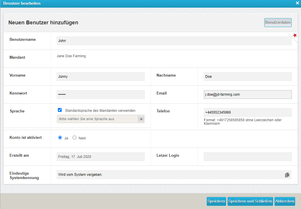
How to Set Up a New User:
- Click on the "New user" button

- Enter an Username, i.e. Firstname.Lastname
- Set Firstname and Lastname. This is important for the notifications page.
- Set a password (The password will show as empty when you save the user or call up the user again)
- With setting the email address and phonenumber fields you let us know how you would like to receive notifications from the raindancer system.
- Setting an email address has also the advantage that the user can reset their password if they need to.
- Select the notification method for this user. SMS or WhatsApp
Entering the telephone number will cause you to receive notifications (for a fee) via the specified channel
- Setting an email address has also the advantage that the user can reset their password if they need to.
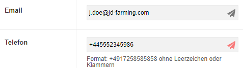
- You can click on the
 Symbol next to the e-mail address or phone number to test the communication with raindancer.

A pop-up window will appear to notify you that a test message will be sent. Click on "Yes" to send the test message. - You can pre-select a different language for the user under "Language".
- Click the "Save" button to apply these settings.
Setting Up Push-Notifications ANDROID
Setting Up Push-Notifications IOS
Permissions (Memberships)
We have now created a new user.
To allow the user to use the app or access the raindancer portal, we have to grant him/her the correct rights/permissions.
-
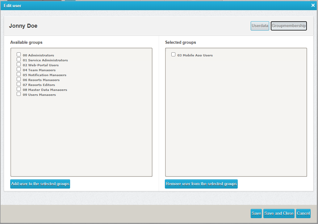
- At the top right position, select "Groupmembership"
- You should see two columns.
On the left you have the available groups which you can assign to the user.
On the right side you see already assigned groups. - To assign a group to the user, tick the box next to the group that you want to assign to the user and click the "Add user to the selected groups" button.
The selected groups should have moved over to the "Selected Groups" column.
Click on the "Save and Close" button to complete the user setup. - Optionally, you can select which notifications your users should receive. Further information can be found here: Notifications
- At the top right position, select "Groupmembership"
Membership Groups
A brief explanation about the available membership groups:
| NR | NAME | EXPLANATION |
| 00 |
Administratoren |
Full access on your system |
| 02 | Web-Portal Users |
User can log on to the raindancer portal but cannot amend any settings. |
| 03 | Mobile App Users | User can use the App. |
| 04 | Team Managers | Responsible for the optional teams module and assembles teams |
| 05 | Notification Managers | Can adjust / set notifications |
| 07 | Reports Editors | Can edit / rebook completed assignments (May also edit the water quantities later) |
| 08 | Master Data Managers | Can manage crops and soils |
| 09 | Users Managers | Can manage users and corresponding settings |
Setup Notifications
To have employees notified, follow these steps.
How to set notifications
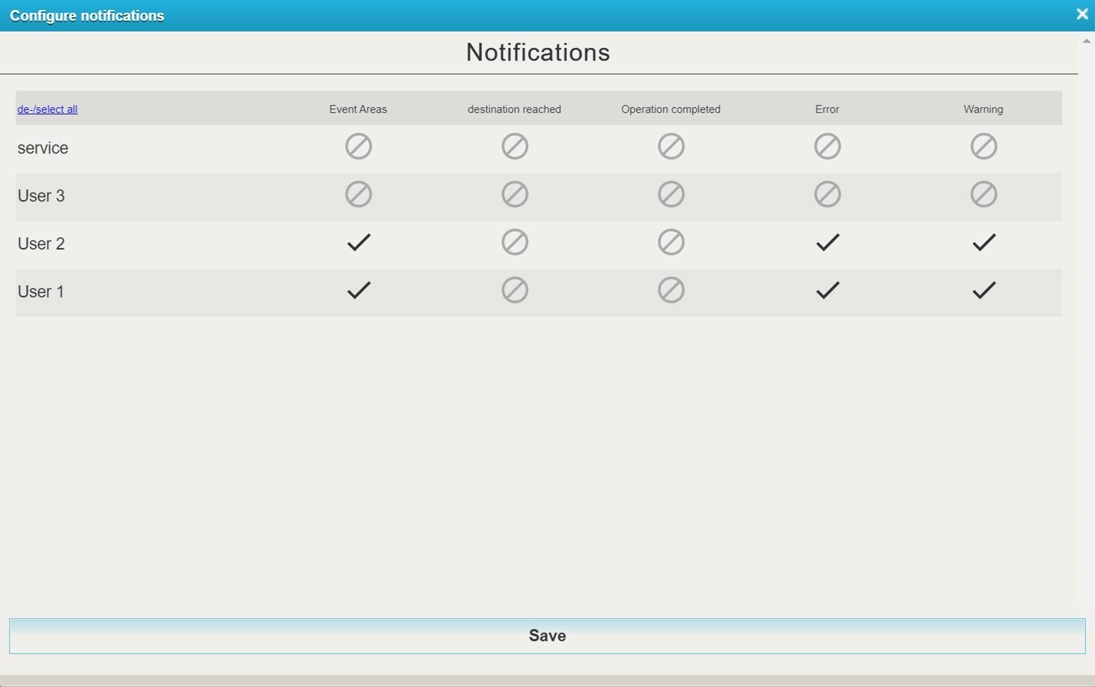
- On the raindancer portal, select Config on the left-hand side, then User
- Click on the Configure Notifications button at the bottom of the user overview
- Tick the box next to the employee
 , to indicate that the selected employee will receive a notification for these events.
  Icons, on the other hand, deactivate these notifications. Clicking on the icons changes the mode.

You also have this option in the Raindancer app. To do this, click on more in the lower menu bar and select Notification Settings.
Explanation of the Events:
- Event Areas:
Event areas are zones that have been drawn by you within your field to, amongst other things it can trigger a notification when the raindancer enters or leaves this zone. - Destination reached:
A notification will be sent shortly before the irrigation run is completed.
The standard setting is set to 25 meters before the target point / hose reel. This value can be adjusted in the settings. - Operation Completed:
The irrigator has reached the target radius and a drop in pressure is detected. - Error:
This kind of events require immediate intervention. Examples of a malfunction could be a tipped over gun carriage or a too high water pressure. - Warning:
Warning messages are notifications that interfere with, but do not catastrophically hinder, operation. An example of a warning message would be a low pressure value at the sprinkler.
Create a Well
The term well refers to all water sources that are used for irrigation.
Managing one or more wells is particularly useful if you need to keep track of the quantities of water withdrawn.
What do I need to do?
- In the raindancer portal at the top click on Wells → Wells
- Click on the "New Well" button
- Assign a Name
- Set latitude/longitude.
Note: If you are using the map to set latitude/longitude,
please do not close the window with the x-symbol, as this would close the complete
setup for create/edit the well and all your entries will be lost. - Select the volume or operating time for billing type
- OPTIONAL Select a team if this option has been purchased
- Click on "Save".
Detailed Information on the Inputs
Name
Enter the name for the well here.
Latitude / Longitude
Specify where the well is located. You can enter the coordinates manually. Otherwise, you can also use the map tool, which you can access by clicking on the "Map" button.
Accounting type
Here you specify the billing type for the well. You can choose between cubic metres (m³) and hours (h).
Accounting identifier
Here you can give the well its own identifier apart from the name. This has the advantage that you have several wells with the same identifier and can later filter by exactly this identifier.
Permitted Quantity
Enter the maximum quantity that may be withdrawn from the well here. You will then see how much water has been taken and the maximum amount that may be withdrawn.
Remarks
Here you can leave important information for colleagues / employees.
Teams
Here you specify which teams have access to the well and which do not.
Add Fields and Areas
Fields can only be drawn in the portal using a PC.
Tablets are only of limited use for editing fields and alleys.
Create a field
- Select "Fields" at the top centre
- To create a new field, click on the "Add" button at the bottom
- To edit, click on the edit icon
 to the right of the field to be edited
- To create a new field, click on the "Add" button at the bottom
- Assign a name
- Select standard well
- Select soil, "-" is preselected
- Select crop type
- OPTIONAL Select area
- OPTIONAL Assign a team
- Leave area empty, as the area is calculated by the drawn area
- OPTIONAL Select a Group, if desired
- Click on the "Save" button at the bottom right

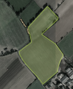
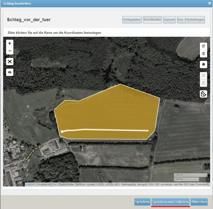
Draw your Fields
- Click on the "Coordinates" button at the top

- Navigate on the map to the area you want to draw. To do this, you can reach into the map with the mouse and drag to the left and right. To zoom in and out, you can use the mouse wheel or the + or - symbol on the left-hand side of the map
- Click on the "New Shape"
 button (top right of the map) to activate the drawing mode for the field area
 - Drawing is done by placing points on the map
- Place the first point, preferably in a corner of your field, and place the remaining points one by one so that the boundaries of your field are mapped as accurately as possible.
The last point should be placed on the first one to complete the field. - Click on the "Save" button to save this new surface. The colour of the drawn area should now be displayed in yellow on your map.
- If you have now finished editing the field, you can finalise this process by clicking on the "Save and close" button.
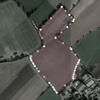
Edit your Fields
-
Click on the edit icon
 on the right-hand side of the map to activate the edit mode
 - The edges of the area are transformed into a line with many points. The white dots are the dots that you have previously drawn. Grey dots are ghost dots, which are only converted to real dot by clicking on them. The grey dots can be used to draw more precise areas.
- Drag these points according to your requirements to create the best possible representation of the surface.
- Click on the "Save" button to save this new surface.
- If you have now finished editing the field, you can finalise this process by clicking on the "Save and close" button.

Field Import
These guide will help you to import your field data from the various sources.
Click on Fields → Import to start the Import process.
Select Your Source
In the Select import type field, select the type of your source files.
You have the following options available
- kml/kmz - This format is used in Google Earth
- shp (Shape) - Many GIS systems support this format
- shp as ANDI - This data format is reserved for farmers in Lower Saxony
Make your decision based on your source material.
Upload Data
Follow the instructions in the system to select the correct files in order to import them without errors.
shp - Shape
If you want to import a shapefile, you must select at least one shp, one shx and one dbf file.
A prj file, which defines the projection in which a shape file exists, should also be selected.
If this is not used, the projection must be selected manually in the next step
shp from Andi
In addition to the files described here under shp, an xml file must also be selected. A prj file is not necessary, as all Andi files are available in the same projection.
Once you have selected the files, click on "Check format". This will transfer the files to the server and further options will be displayed.
For ANDI files, Raindancer usually sets the values of the selection boxes automatically to match the required data.
Projection
If Raindancer cannot determine the projection, you can make a manual selection here.
This should only be the case for shp files without a prj file.
Group
Raindancer is capable of managing multiple field groups. You have the option to input free text to define a new group or choose from the existing groups. To update existing fields with data from the import file, it is required that the field in the database and the fields in the file belong to the same group. If they do not, an assignment cannot be created, and the field from the file will be added as needed.
Filed identifier
The field identifier defines the property by which a field from the file is assigned to a field in the database.
If you select "Do not use import identifier", all fields in the file are considered new fields and no assignment is made.
This can lead to overlapping. This can lead to unpredictable behaviour. Make sure that the fields are not exactly "on top of each other".
The preferred option is "Use geographic area for mapping".
This option enables Raindancer to compare the geographical position of the field in the file against that in the database. If there is sufficient overlap between both fields, an assignment is made. The new field must match at least 90% of the old field - if this criterion is met by multiple fields, the one with the smallest area outside the intersection is chosen.
All other options are associated with a data column in the field file.
Field Identifier and Field Number
All the data columns from the file are displayed. The values from the selected column are utilized as the field identifier or the field number.
Field Name
All the data columns from the file are displayed. The values from the selected column are used as the field names.
The select boxes each give you an example of the data contained in the column Look carefully for your desired data.
Area Calculation
Select the area calculation method that suits you best.
For your first import, it is advantageous if you have the area calculated using the geodata.
The appropriate option for doing this is calculate area if no area is available yet
Crops
Here, you can select a file column from which the crop type is to be obtained. For each value in this column, a new crop type is created in the system if it does not already exist and assigned to the corresponding field.
Update existing field properties
- Crops
- Number
- Name
of assigned fields in the database is updated.
Update Existing Field Coordinates
The geography of an assigned field in the database is only updated if this option is set.
Deactivate fields that are not present in the import
If the fields have been assigned by geographic position, all fields in the client that are not present in the field file are deactivated.
Do not add new fields from import and only include existing fields
No new fields are created, only updates to existing fields in the database.
Event areas - Getting started
You can draw event areas on your fields to trigger actions there.
When the irrigator (the trolley) "enters" and/or "leaves" these areas, the following actions, among others, can be triggered:
- A notification is sent to employees / free phone numbers
(e.g. information that the angles need to be set differently / precursor to sector control). - Change the precipitation/speed (variable rate irrigation)
e.g. for clay banks, dips etc. (prerequisite is remote control of the reel) - Stop the irrigation
For irrigators that run with our sector controls, settings can be stored for the marked areas, e.g:
- Allow irrigation (e.g. for irrigation beyond the field boundary)
- Prohibit irrigation (e.g. to maintain a safe distance from the road)
- Adjusting the stop angle for an area
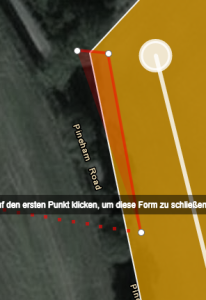
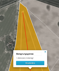
Draw in event areas
Event areas are marked in red.
- Click on the "New shape" button (top right of the map) to activate the drawing mode for the impact area
- Drawing is done by placing points on the map
- Set the first point and set the remaining points one after the other so that you map the event area as closely as possible.
The last point should be placed on the first one to complete the drawn area. -

Setting marker points

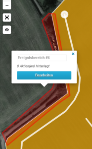
Finished event area
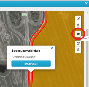
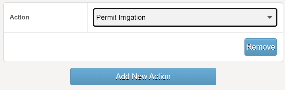
- After you have drawn the event area, please click on the "Edit" button
- Click on the "Add New Action" button here

Here are some examples:
-
Send a message to an employee when reaching or leaving a marked area
-
If you select "Send command" here, for example, you can, among other things :
-
Stop the irrigation
-
Change the irrigation quantity
-
Change the sector
-
Preventing/allowing irrigation
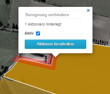
The "Prevent/Allow Irrigation" feature enables you to designate zones for sector control where irrigation is either prohibited or permitted beyond the field's boundary.
For instance, you can establish safety margins from roads or specify zones for irrigation that extend past the field's edge.
Ensure that zones marked for "Allow Irrigation" begin within the field boundaries—areas drawn adjacent to the field will be disregarded.
It's beneficial to know that these zones can be activated or deactivated via your smartphone. This allows you to irrigate based on the current usage of adjacent fields and adjust for wind conditions to avoid areas such as roads.
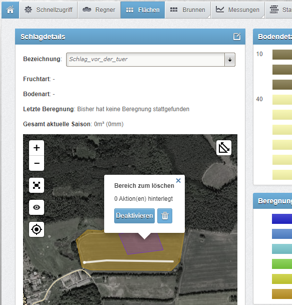
Delete or Deactivate Event Areas
You can easily deactivate or delete the event area of your choice via the "field detail" page or in the Raindancer app.
To do this, click on the event area that you want to deactivate or delete.
A new button will appear ![]()
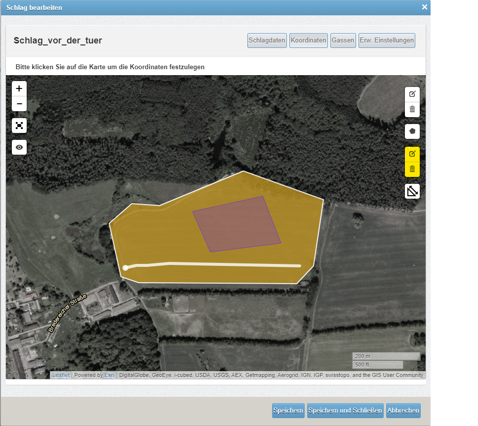
Delete event areas in field editing
You can effortlessly deactivate or remove the desired event area through the "Edit field" page. Simply click on "Coordinates" within the Edit field page. To delete an event area, select the lower trash can icon on the right side, choose the event area you wish to delete, and then click "Apply".
|
|
|
|
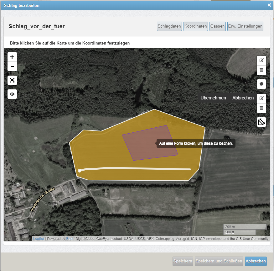
After you have clicked within the event area, it disappears from the map. Click on Save to apply the changes.
Event Areas and their Actions
Overview
It is possible to draw areas on the fields to trigger one or more of the following actions when entering or leaving:
- Send a message with customised text
- Send a command
- Stop active irrigation REMOTE CONTROL
- Change irrigation amount REMOTE CONTROL
- Change irrigation sector SECTOR CONTROL
- Set extended outputs REMOTE CONTROL
- Avoid irrigation SECTOR CONTROL
- Permit irrigation SECTOR CONTROL
- Cornering programme (for self-propelled) REMOTE CONTROL
Drawing in the Areas
How are these event areas and the corresponding actions stored?
To do this, select the field via Fields and go to Edit field, here to Coordinates.
Draw an event area via Create new shape ![]() .
.
(at the bottom right, you will see a dimension bar to help you draw the shape if you switch to "Full screen"  beforehand). When drawing, the last click must always go back to the first click.
Now edit the event area and select one of the options under Action.
Sending a message
You can send a message to yourself or another person, such as an employee, when the irrigator enters or exits an event area.
To achieve this, input the desired telephone number in the 'Recipient' field.
Sending a command
You can use the event areas to trigger one of the following commands when entering or / and leaving the event area.
- Stop active irrigation → Stops the current irrigation.
- Change irrigation quantity → Changes the amount of water in absolute (mm or m/h) or relative (in per cent) terms.
- Change irrigation sector → Adjusts the sector control.
- Avoid irrigation→ Prevents irrigation of the event area
- Permit irrigation→ Allows irrigation of the event area
- Set extended outputs
Special areas for sector control
There are areas that have been specially designed for sector control. These areas allow you to customise the sector control specifically to your requirements.
Change irrigation sector
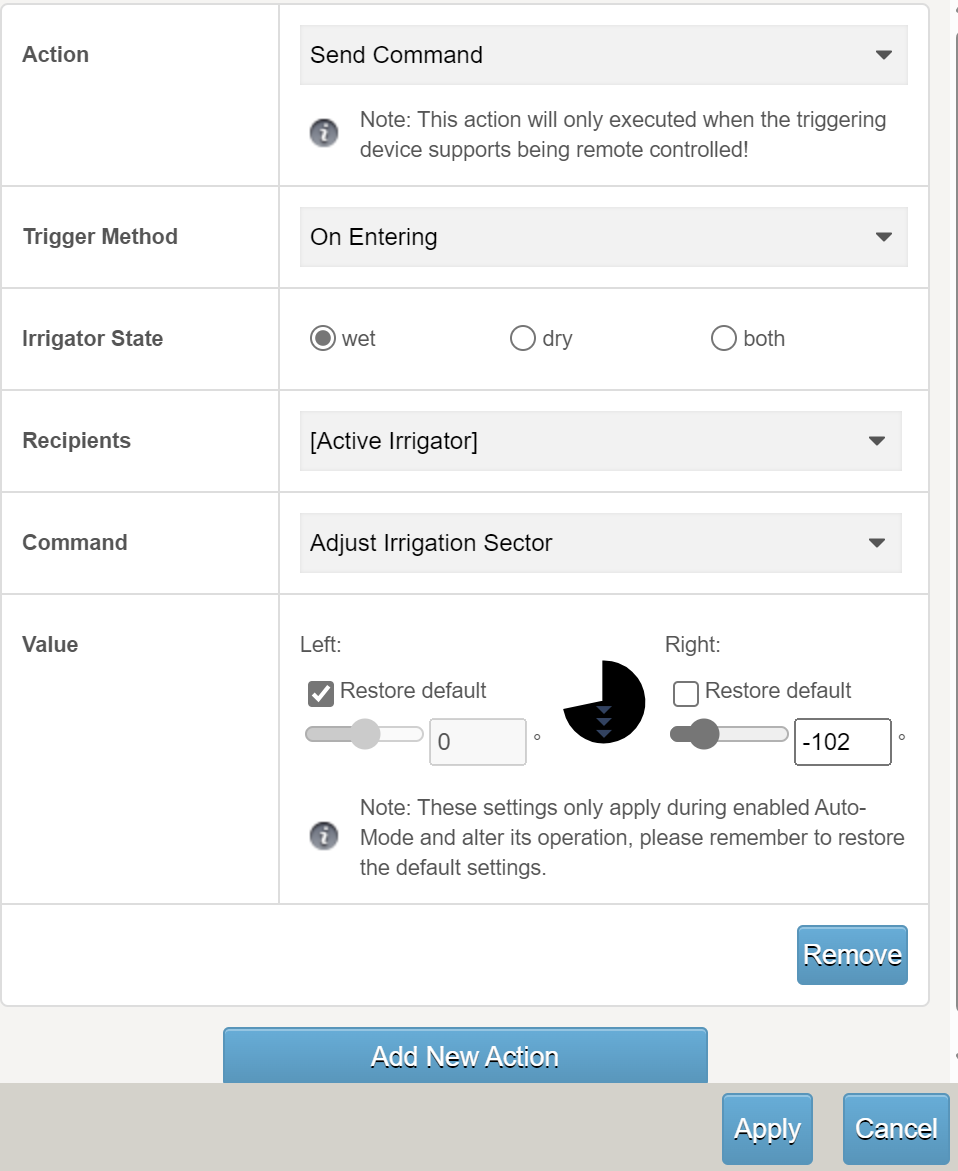
Here, you can specify the left and/or right stops for the drawn sector. Of course, it then takes the field boundaries into account based on these new stop angles.
When leaving the drawn area, you can switch back to the default (restore default).
If you do not enter anything for "on leaving", the settings for this irrigation programme remain active.
The default values will then be active again for the next operation.
Do not forget to Apply and Save!
Avoid Irrigation
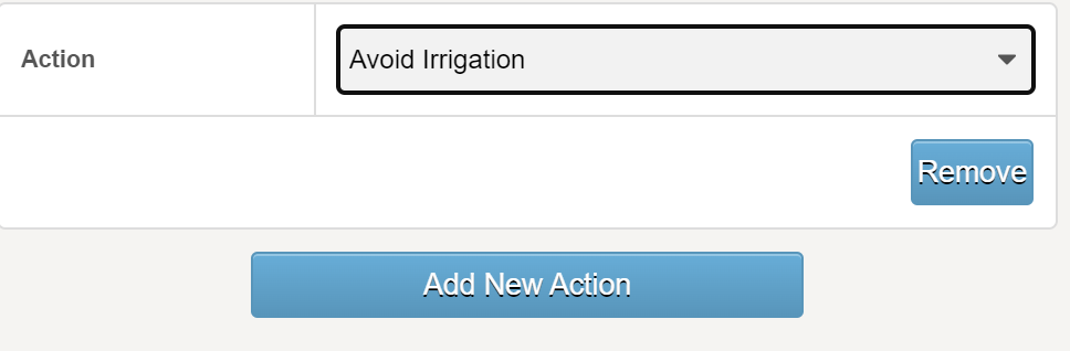
Example: You do not want to irrigate an area (e.g. a strip along the motorway) for safety reasons.
Then select the Avoid Irrigation action in the "Action" field.
Permit Irrigation
Example: You want to over-irrigate an area (e.g. a strip along the woodland border) to ensure that all the plants in your field get enough water.
Then select the "Permit Irrigation" action in the "Action" field.
Prevent double irrigation
Mark the "Avoid irrigation" area between the two Runs. Each run now only irrigates up to this area so that double irrigation is prevented.
This line should be a very narrow area - a triangle, for example. When drawing, the last click must always go back to the first - the area must be closed in this way!
Create a Run
Irrigation runs permanently stores the path of the irrigation machine in the system. This information offers several advantages in the daily use of the Raindancer app and sector control.
Why do you need runs?
- Length of the irrigation path
If an irrigator starts on an run, the Raindancer recognises this and the length is known immediately. - Positioning of the hose reel
Especially if you do not position your hose reel exactly at the border of the field, e.g. in the headland, the irrigation system may not reach the field border. The exact location of the hose reel (the target point) is determined by the run. - Do you have irrigators that also run in a "curve"?
You can also use runs to draw curved paths.
This is particularly important if you are working with sector control to calculate the stop angles correctly. - Information on when and how much was irrigated here.
This is permanently displayed on the run:
- Last irrigation with date and quantity
- How much was irrigated on the alley in total this year? - Irrigation runs serve as the basis for certain reports.
Certain analyses within Raindancer rely on the allocation of water to specific sub-areas of the fields, such as the field evaluation report. - Runs are the basis for operational planning/implementation
Creating Permanent Runs from old operations
Once irrigating a field, you can create permanent runs from old irrigations. The runs
then remain permanently available.
This is how it works ...
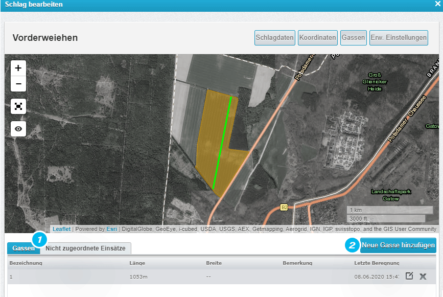
Select the field and go to edit  , then go to "Runs" [1]
In the table below the map, please go to " Unassigned operations" [2]
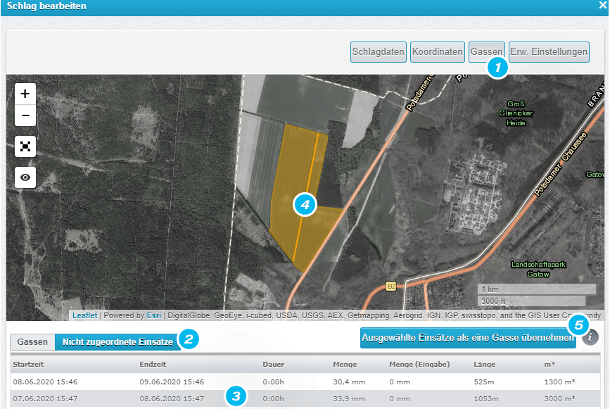
You can see all irrigation operations here.
Click on an run [3] to see it on the map. [4]
If you now click on the "Take selected missions assignments to a run" [5] tab at the bottom, an alley has been created.
Do the same with the other missions until you have created all the runs.
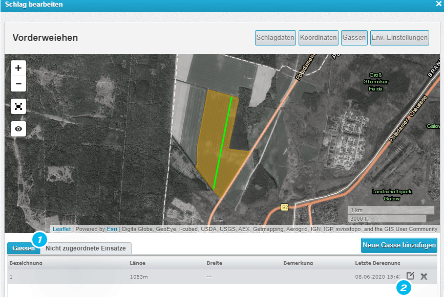
If you click on the "Runs" tab [1], you will see the transferred runs.
If you click on the Edit icon [2], you can change / add details for the run.
e.g. for irrigation in the headland width on the left side only 20 m.
Depending on the respective width, a semi-transparent area is displayed next to the run, which shows the working width,
to ensure a more precise marking of the run.
These two values (left and right width) are then used to visualise and calculate the irrigated amount.
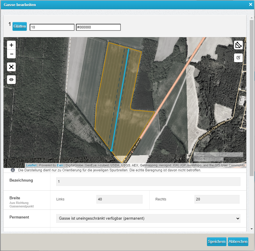
Left / right always with a view from the hose reel to the trolley!
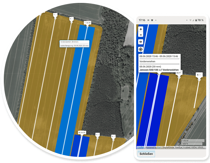
The runs are now permanently displayed on the fields with the information: when was the last time irrigation was carried out here.
Click on the alley to see the mm of the last irrigation and the total mm.
Of course also on the smartphone.
Draw a Run
- e.g. irrigation in the curve
A conventional hose reel can also irrigate in an arc, such as along the border of a field.
However, when using a hose reel that isn't self-propelled (unlike Fasterholt machines, which are), Raindancer will always plot a straight line from the starting point to the target. This typically isn't an issue, but with sector control, if the actual direction doesn't align with the start-to-target line, the stops could be miscalculated.
Therefore, it's advisable to manually draw these paths as runs.
You can now use the icon ![]() at the top right to define the run using several points.
at the top right to define the run using several points.
Click with the mouse on the symbol for Add new Run highlighted in yellow in the image below.
Now draw the run on the field with the software.
Start where your hose reel stands!
Complete the drawing of the Run by double-clicking on the last point you set for the Run.
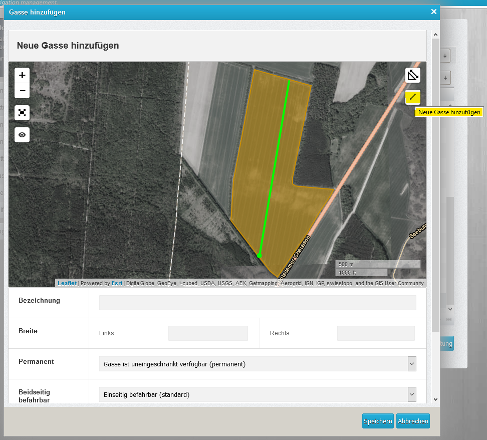
Give the run a name and add the width of the left and right sections of the respective Run.
If you wish, the Run can be deleted automatically after irrigation. To do this, change the settings in the Permanent field to "Run is available for one-time irrigation". Runs are always created "permanent" by default.
You have the option of changing the default setting "Permanent" to "Always once" in the advanced settings.
If you only want a specific irrigator type, such as a classic hose reel, to use a Run, select the relevant irrigator type from the list.
The irrigator that do not correspond to the irrigator type will ignore the Run. This prevents misunderstandings when automatically assigning Runs and irrigators.
If you wish, you can set whether a Run can be used on one or both sides. To do this, simply select the corresponding menu item under "Passable in either direction".
Permission for corner programmes allows you to set whether corner irrigation is allowed without having to change the setting on the irrigator.
You can find more information on the corner programme in the [irrigator control].
You can select Magnetic if you are sure that you have drawn the Run correctly.
This makes the sector on field boundaries more stable and does not constantly move back and forth two degrees, which saves the battery.
When the machine now irrigates on this Run, it knows the feed direction, length, etc.
If you are working with our sector control, the stop angles are calculated based on the current direction
When a machine initiates irrigation, it searches for the nearest "Run". This implies that it can execute runs on lanes that aren't identical to the real world - the Raindancer will find the Run regardless. Consequently, if two irrigation runs begin in proximity, both should be drawn to prevent the Raindancer from switching to an incorrect Run if it doesn't detect nearer one.
Deleting irrigation runs
- If you have not yet selected your field, proceed as follows:
- Select fields at the top centre
- To edit, click on the edit icon to the right of the field to be edited
- Select fields at the top centre
- Select Runs at the top right with a click
- Under the map under Runs listing, click on the icon
 to the right of the Run you want to be deleted
 - A pop-up window appears, asking you if you really want to delete this Run. You can confirm this by clicking on Yes.
- Click on the Save and close button at the bottom right to finalise the editing of the areas.

Auto Speed - The cruise control for irrigation
Automatic Speed adjustment via remote control on the hose reel
To use Auto Speed, you need an SMS or Internet control on the hose drum that allows you to set the speed.
Follow this guide to set up the control system
What do I have to do
![]() Set the irrigation amount in mm.
Set the irrigation amount in mm.
![]() The retraction speed is calculated and transmitted to the machine based on the nozzle diameter, the pressure and the working width.
The retraction speed is calculated and transmitted to the machine based on the nozzle diameter, the pressure and the working width.
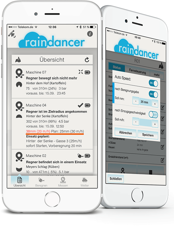
Manual adjustment of the irrigation quantity
(without remote control on the hose reel)
In the Raindancer app, you can specify the desired irrigation amount in millimetres. Once irrigation begins and pressure is applied, the app displays the necessary retraction speed in meters per hour.
Here's how to use it:
Select the drum icon and navigate to Auto Speed.
![]() Here, you can input the desired millimetres. This value will remain until you decide to change it.
Here, you can input the desired millimetres. This value will remain until you decide to change it.
![]() Once pressure is applied, the app will indicate the appropriate speed to achieve this millimetre dosage in the plan values.
Once pressure is applied, the app will indicate the appropriate speed to achieve this millimetre dosage in the plan values.
Please note that any subsequent changes in pressure are not automatically adjusted for; to manage this, a remote control for your reel is required.
The Master Data - Crops and Soils
Within this section of the Raindancer System, you oversee the management of crops, units, and soils.
Entering the types of crops enables quick identification of which crop is cultivated in each field when viewing the field section.
It's possible that after importing, the names might be represented as numbers. These can be modified at any time subsequently.
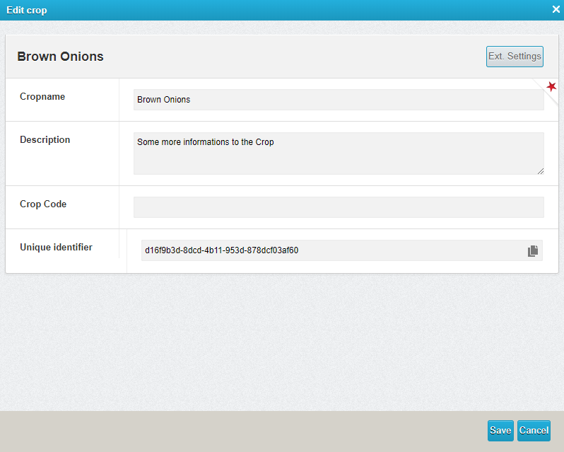
Customise Your Crops
Crop types are mainly used to provide a clear overview of the various lists. They make it easier for new employees to find their way around.
- In the raindancer portal, select Master Data at the top right, then Crops
- Click on the edit icon
 to the right of the crop you want to edit
 - To create, click on the "Add new crop" button at the bottom left
- Click on the edit icon
- Here you can change the crop name and description fields
- Optionally, you can also adjust the irrigation cycle by clicking on "Extended settings" (top right). The default value is set to 10 days. Changes can be saved by clicking on "Save and close".
- Confirm by clicking on the "Save" button.
Soils
Preparing soil is only necessary if you intend to irrigate weather stations or on demand.
A catalogue offers 12 distinct soil substrates for this purpose. They can be assembled into 10 cm blocks to create the soil. This soil can then be applied to fields for determining soil moisture. The layered substrates yield a staggered field capacity at depth.
This value indicates how well a soil can hold water against gravity.
-
In the raindancer portal, select Master Data at the top right, then Soils types
-
To edit, click on the edit icon
to the right of the soil you want to edit -
To create, click on the "Add new soil" button at the bottom left
-
-
Here you can change the Soil name and Description fields
-
After saving On the Substrates tab, you find the option to structure your soil from top to bottom.
-
Confirm by clicking on the "Save" button.
Plan Future Operations
This section of the Raindancer portal is designed to enable you to plan your assignments in advance and thus bring more structure to your work dynamics.
You will find the operation scheduling in the portal on the left-hand side in the ribbon.
Runs to your fields are required for planning operations. See also Create a Run
Plan New Operation
To plan a new deployment, navigate to the " Operations Schedule" item via the left-hand bar.
Click on the "Operations Schedule" area to access the overview of all planned operations. So that you can plan a new missions,
Click on the "Plan a new mission" button in the bottom right-hand corner.
Select the Field
A new screen will open in which you can select the field on which you plan your operation. If you have numerous fields, you can also search for a specific field by entering the name in the search bar.
Select your Irrigator
Once you have decided on a field, the next step is to select the irrigator you want to use on the field.
Once you have completed both steps, you will see the new planned application in your overview. By clicking on the application, you will be allowed to edit it in more detail. You can then change the irrigator, set or adjust the feed speed, specify the amount of water per mm, change the sequence and make a comment.
You can print out all of the planned operations on paper. To do this, click on the "Print" button in the bottom left-hand corner. You will now see a print preview.
Delete
If you want to delete the operation, you can also do this in the operation overview. You will find the symbol of a recycling bin
Units - Metric or Imperial
Changing the units in the Raindancer system is centralised and affects all outputs in the entire system.
You can find the settings for this under Master Data ⇾ Units
At the top you will find the switch between a predefined metric set of units or an imperial set of units.
Conversion between the metric and imperial systems can lead to unusual rounding and decimal values.
Under the simple switching between the systems you will find the individual unit categories used in the Raindancer system.
To change individual units, uncheck Use default and then select your preferred unit from the selection box.
Click on Save and your system will now show you the selected unit in the selected category.
Irrigatior Control - Remote control of irrigation
Access to the control system is a pivotal aspect of operating the Raindancer for your irrigation machinery, provided that your equipment includes at least an SMS-based control system.
By adjusting the intake speed according to the volume of water dispensed and the operational width, you can optimize water conservation through AutoSpeed.
Setting up the control system
You can find the setting to save the irrigation machine in the upper menu ribbon under Irrigators. Here you can then select the machine for which you want to save the controller or create a new machine using these instructions,
Then click on the Edit button and switch to the Setup and Controls tab.
At this point, select the make of your irrigation computer from the selection. Different models and variants from various manufacturers are available here.
Please ensure that your computer has the option of being controlled via SMS and that the computer has been configured in accordance with the instructions for your specific make to ensure smooth integration.
Follow your manufacturer's instructions to achieve communication with the Raindancer system.
Telephone Numbers
A telephone number must be saved in your computer to which replies can be sent.
| +31 97014444993 |
In addition to SMS control, if a compatible API is set up, you can choose API control for an irrigator through the control type option. To ensure the control functions properly, select the API name given during the setup process and input the identification extension, such as the serial number, for the device's corresponding API.
BEINLICH 2KR/H
Make sure that your irrigation computer is operated in Raindancer mode. Otherwise, the system will not be able to process the machine's responses correctly.
Phone no.
This field is visible for SMS-based control types.
Please enter the telephone number of your irrigation computer here.
API-Name
OPTIONAL
This field is only visible for API-based control types. Enter the identifier of the device used for the API here.
Control Unit
OPTIONAL
This field is only visible for API-based control types. Enter the identifier that was assigned during the API configuration here.
Raindancer GPS Modul
This section deals with the maintenance and servicing of the GPS modul.
Installing the GPS module correctly
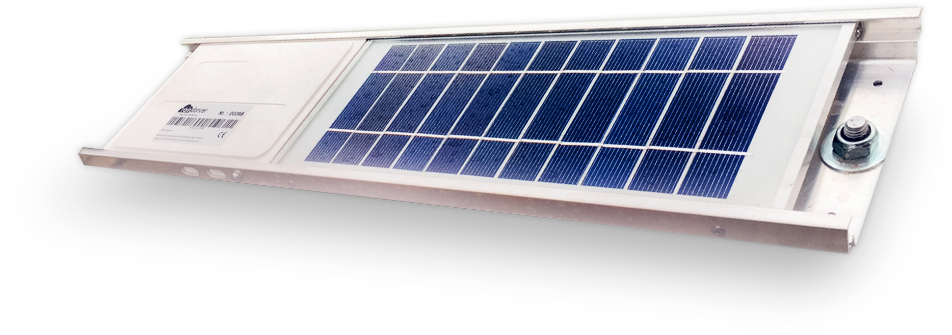
Introduction
We leave the installation of the solar module up to you. You should ensure that the solar module is mounted horizontally on your gun carriage construction with a clear "view" of the sky. Shading of the solar panel should also be avoided for the best efficiency.


Installation
- The raindancer GPS solar panels are mounted on the gun carriage in a horizontal position, fastened.
A raindancer mounting kit is available for installation. The mounting can be very different depending on the existing sprinkler stand. Most customers mount the Raindancer by means of welded flat bars. - The pressure sensor should be mounted near the gun and preferably vertically from above. The "upside down" mounting should prevent water or other deposits from remaining in the sensor. If you have an existing ¼ inch connector in a horizontal position, we recommend using an angle piece to guarantee the "upside down" mounting.
- You must not shorten cables that are too long, but fix them with cable ties.
Assigning the Solar module to the irrigator
If you order a GPS module, we will put it into your client's system upon delivery, and you can then assign it to the irrigator to which it was attached to.
Precision
If a device has been stored indoors or other places with poor GPS signal coverage for a long time, it may take some time to return to normal precision (usually a few minutes, rarely up to an hour). Buildings or similar in the surrounding area of the GPS device also limit the sight on the satellites and therefore the accuracy.
Summary of the initial setup
- GPS solar panel is mounted horizontally
- Pressure sensor is mounted "upside down" near the gun
- Do not shorten the cable, only fix it in place
- GPS module is assigned to a irrigator
- GPS module is set in summer mode
Reset the Module
To reset the module, you need the reset stick.
Simply insert this reset stick into the appropriate connector on your Raindancer module. It is the port to which the pressure sensor is usually connected.
Connect the reset stick straight and pull it straight out again. Never wiggle or twist the reset stick
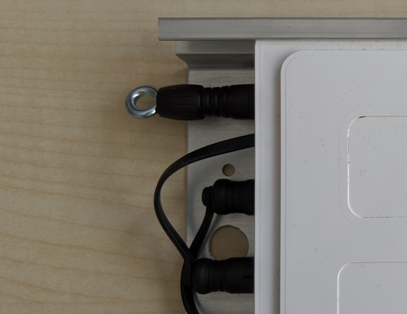
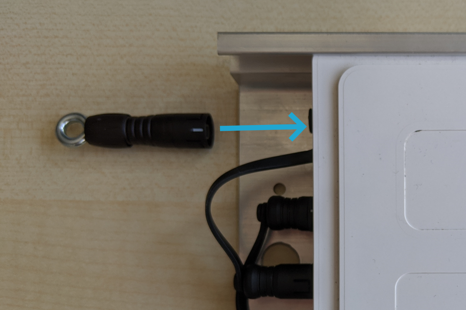
Wait a few seconds and disconnect the plug again. The device will then restart and the connection should be re-established within a few minutes.
Of course, your previously recorded irrigation data or information about fields etc. is retained.
Which Devices Can I Reset?
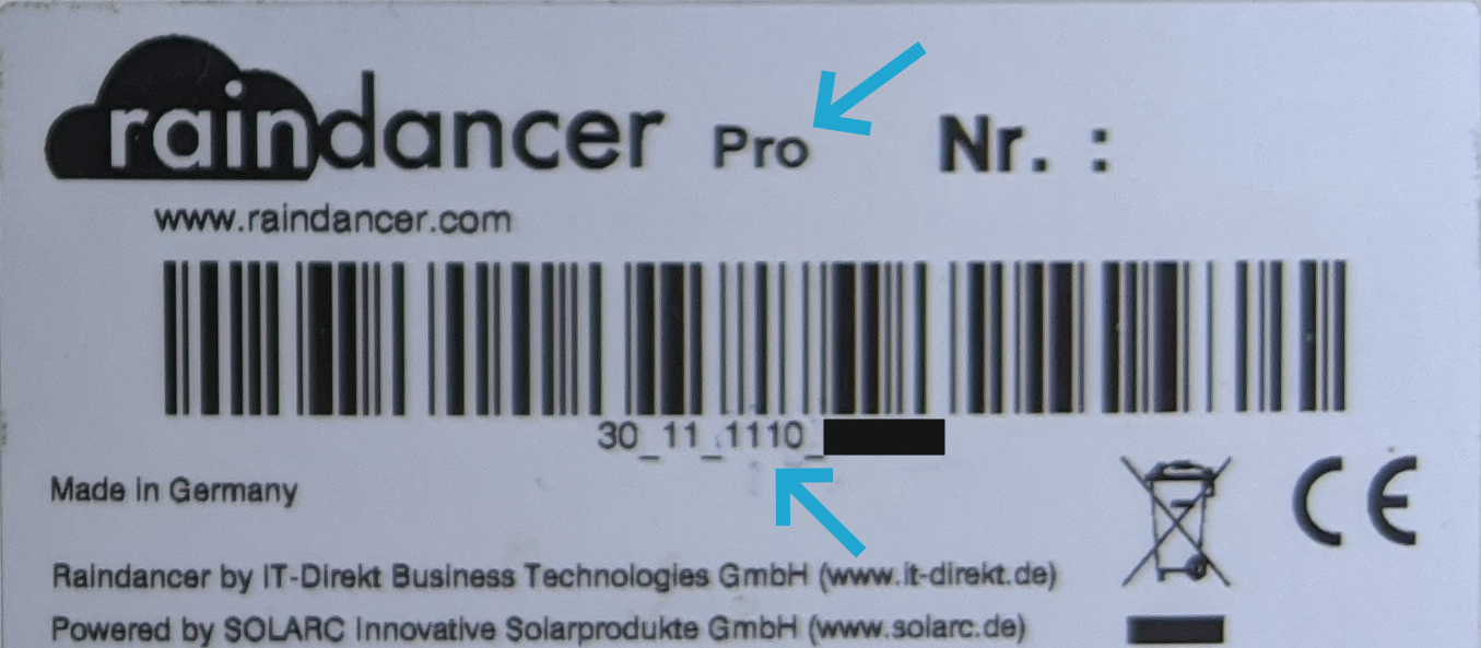
You can recognise a Pro device by the "Pro" suffix on the identification label or by the serial number.
Please note that this procedure only works with Pro devices and second-generation standard devices.
You can only recognise a standard device by its serial number.
Serial number of a Pro device:
XX_XX_X1X(X)_XXXXX
Serial number of a second generation standard device:
XX_XX_XX2(X)_XXXXX
The X stands for any number. For some serial numbers, the bracketed (X) is not present
Maintaining and Cleaning the Solar Modules
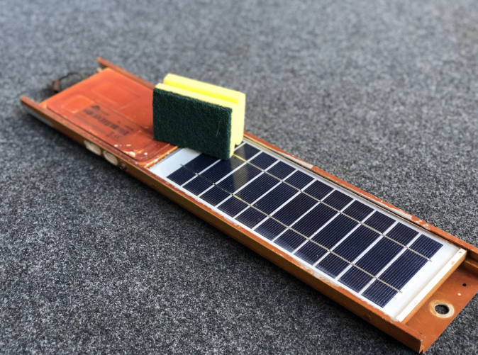
If the solar module is dirty, you can clean it with a cleaning sponge with the "hard cleaning side"
- Solar panels must not be cleaned with high-pressure cleaners.
- Do not use aggressive chemicals to avoid damaging the seals.
- A kitchen sponge with the rough green side has proven to be effective. A soap pot sponge with steel wool from the drugstore has also achieved very good results.
Storage in the Winter
If your irrigator is stored indoors for several days, the solar module will discharge.
You should allow approx. 2 days for charging after discharging in good sunlight. We recommend that you put the solar module into hibernation in autumn - it will then only transmit its position once a day.
Of course, you will need to "wake up" the module again before using it in spring. You can trigger both scenarios in the irrigators in the portal. You can connect the module to a charger so that it is immediately ready for use after a longer period of storage. You can order such a charger from us.
Before you drive the irrigator into the hall, please switch the Raindancer units in the Raindancer Portal (https://portal.) to winter mode. This ensures that the batteries are preserved and do not discharge completely during the winter. Storing the modules with fully discharged batteries has a negative effect on the durability of the batteries.
To maximise durability, the Raindancer modules must be dismounted in winter and stored frost-free.
Make sure that your pressure sensor no longer has water in it.
Due to physical forces (adhesion), water may remain in the pressure sensor even when the machines are empty and these may be destroyed by frost. If the machines are not stored frost-free in winter, the pressure sensors must therefore be removed and stored frost-free.
Pre-season preparation
Please remember to bring the devices into the sun early enough to charge them. A few days are sufficient in sunny weather. On cloudy days, considerably more time is required (you can also order optional chargers).
Switch the devices in the portal (https://portal.myraindancer.com) back to summer mode
(devices are supplied in winter operating mode).
Using the Raindancer Power Supplies
Raindancer power supplies help your solar panels stay reliably charged, even when there's no sunlight.
Before you get started, here are a few important points to keep in mind:
Correct Interpretation of Battery Status
The battery status displayed in the app always represents the status at the last connection. Therefore, the indicated battery voltage becomes meaningful only after the Raindancer panel resumes regular communication.
Recommendations for Use
-
Startup:
Connect the power supply. -
Charging After Longer Downtimes:
Charge the device for at least 8 hours to ensure the battery is sufficiently charged. -
If No Connection emerges:
If there is still no system connection after 8 hours, perform a reset. Ideally, use the reset plug provided. Alternatively, disconnect the power supply from the power source briefly, then reconnect it. -
For Deeply Discharged Batteries:
If the battery was deeply discharged, leave the device connected to the power supply for up to 24 hours. By this time, a connection to the system should be established. -
Capacity When Fully Charged:
A fully charged device lasts approximately 3 days in Summer Mode without sunlight. Use the energy-saving Summer Mode to extend this period by up to 2 additional days, or Winter Mode for several weeks. -
Charging During Regular Operation:
A device that is already regularly communicating typically reaches a full charge within a maximum of 8 hours when connected to the power supply
The Sector Control
Thanks to various start programmes, conventional irrigation preparation is no longer necessary.
The angles automatically adapt to the shape of the field or existing obstacles and can be adjusted at any time. If the irrigation aisle is narrowed, the speed is adjusted accordingly.
You always retain full control, as a manual operating mode with app remote control is also available, which can be particularly useful in changing wind conditions.
Install Sector Control correctly
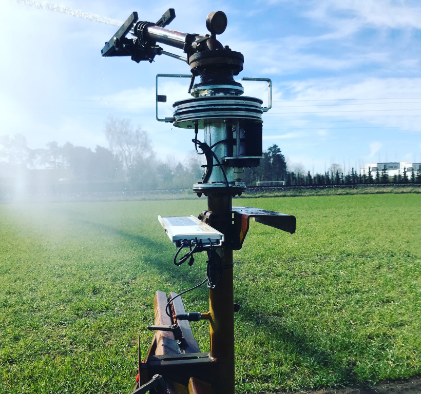 Mounting a Sector Control on a Irrigation Trolley.
What do I have to do?
- Remove the cannon.
- Remove the cannon stops.
- Place the seals between the flanges.
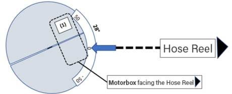
- Align the sector control so that the blue motor box faces the hose reel.

- Fasten the supplied screws.
- Mount the gun with the supplied gasket directly above the sector control.
-
Now mount the provided stops which are fitting for your gun.
Screw the short stop always to the upper position from TOP, and the long stop to the lower position from BOTTOM. - Switch on the sector control on the black motor box. Make sure that the button is pushed in.

Alignment of the Stops
The tip of the triangular markings on the stops must ALWAYS point towards the gun lever.
|
Standard Setup |
Reverse Setup |
|---|


Initial start-up of the sector control
After mounting it is important to configure the sector control for the first time.
Read the Zero Position From the Sector Control

ero Position: Please hold (or stick) the included sticker with the angle indication in a way that the zero mark points towards the hose reel. Now you can read off the zero offset at the groove between the cover plates (here 28°). Please take care to note if + or – (+28° or -28° for example).
For irrigators with a lever located at the rear (e.g. Nelson), please add 180 degrees to this value.
Please enter the zero position offset into the app (see below).
Settings in the Raindancer App
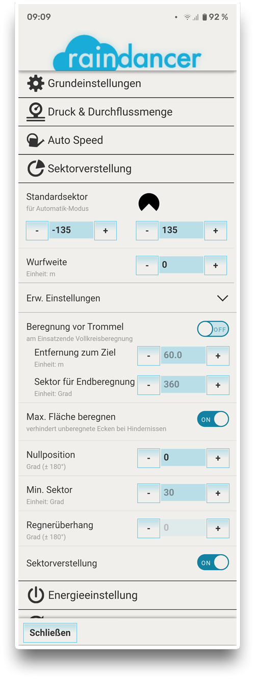
Click on the irrigator and go to the buttons "More" -> "Settings" -> "Sector Adjustment", here you must "activate" (ON) the Sector Adjustment.
With "Save and Apply Settings" your settings will be stored, and you will find more options in this section.
Now you can enter the basic settings.
Default sector: Here you enter the angle at which you wish to irrigate by default. (e.g. -135 / 135, if you water at an angle of 270°). The orientation of the schematic image is corresponding to the point of view that you have when you look from the hose reel towards the gun!
Please take care to note if + or –
Throwing Width: Raindancer uses the throwing range for calculating the correct angle of the stops.
Irrigation in Front of the Reel: For example, if you irrigate at 270°, you can set it to automatically switch to full-circle irrigation 60 m in front of the reel, to distribute water at this place as well.
Irrigate Max. Area: Should be set to "ON" - it will enable the Sector Control to irrigate into the corners in case of an obstacle.
Zero Position:
See above. Please take care to note if + or –
You enter this value only once after installation!
See further information for Overhang
Overhang
Click on the irrigator and go to the buttons More → Settings → Sector Adjustment → Ext. Settings
Measurement
Sometimes the point to which the stop is set does not correspond exactly to the point at which the gun changes the direction of the pan.
To account for this variance, you can measure the gun overhang (see diagram) and then store it for the irrigator in the app.![]()
Before irrigation - Checklist
Before each irrigation, it is necessary to prepare the sector control to ensure trouble-free operation from the start.
A connection to the Raindancer is usually only made every 7 minutes!
The correction of the stops is therefore not done immediately.
Checklist
- Release the Clutch.
- Make sure that the arrows on the stops of the sector control point in the direction of the switch lever
- The switch lever must not be engaged.
- ❗Please ensure that the switch lever is stable enough not to jump over the stops.
- Adjust the left and right stops so that they do not water too close to the field boundaries
- Engage the Clutch.
- After a few minutes, the stops automatically adjust to the field edges.
Special case for guns with reverse switch levers.
The procedure is mostly identical. The direction of the stops is also in the direction of the switch lever. Make sure that the gun does not irrigate beyond the field borders in this setup as well.
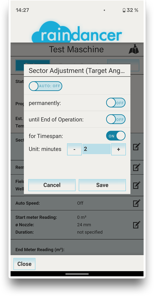
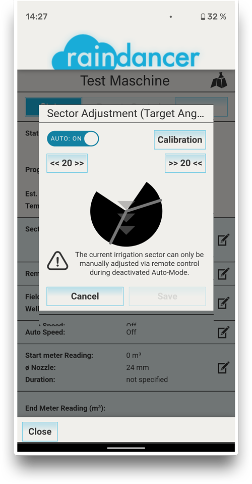
Manual Sector Control
Basically, you have two operating modes with the sector control:
-
AUTO:ON ⇾ You let Raindancer calculate and automatically set the stop angles
-
AUTO:OFF ⇾ You switch off the automatic system and set the stop angles yourself
To set Auto:On/Off, go to the irrigator, then to the Sector Area.
Here you will find the "AUTO" switch for switching over.
You normally work in automatic mode (AUTO:ON).
The stops are calculated by the raindancer and set automatically.
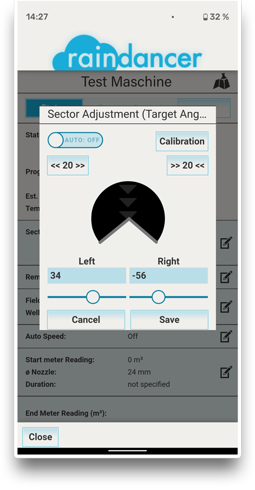
Manual Adjustments
If you want to set the stop angles manually on the smartphone, switch to AUTO:OFF
You will now be asked whether you want to switch ...
- Permanently - i.e. until you later say yourself: now it should "automatically set the sector" again
- Until the end of the operation - i.e. only for this gear
- For a period of time (e.g. 120 min) - i.e. for a limited time, after which it will switch back to automatic sector control.
When could this be done?
e.g. if a stop is to be set to 50° for 2 hours when the wind is blowing in the evening.
The connection to the raindancer is usually only established every 7 minutes!
The correction of the stops is therefore not immediate.
Transport the Sector Control
For transport, you should fix the gun (e.g. with a rope) or fold up the stop on the gun.
Otherwise, the gun may hit the stops and bend them during transport
Alternatively, you can simply decouple the stops of the sector control.
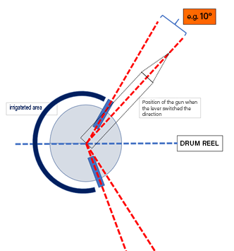
Choosing The Perfect Angle
How do you actually set the stops on the gun to ensure the most even water distribution possible?
We therefore took the time in late summer to take some measurements.
The water distribution of an irrigation run naturally depends on the setting of the stops - we compared a full circle irrigation 360° or 180° with a 270° limit stop setting.
According to our analyses, the water distribution looks roughly as follows:

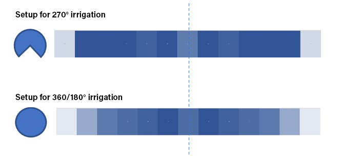
The 270° setting clearly allows more water to reach the outermost areas.
This does not really answer the question - which setting is "better"!
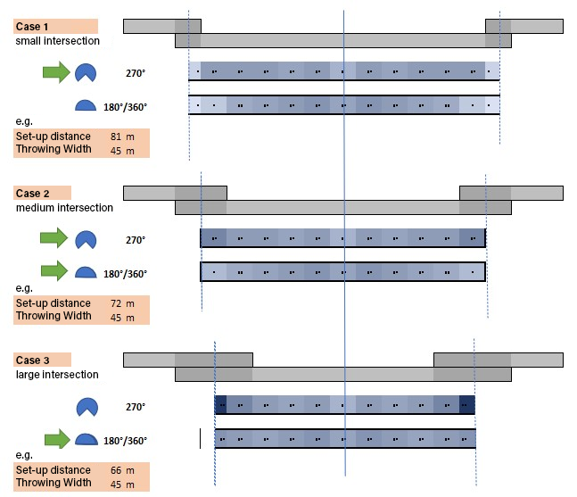
Intersection
Certainly, calculating water distribution must consider the "neighbouring runs," since the throw distance often exceeds half the working width. Consequently, with each operation, we irrigate a portion of the adjacent runs on both sides, which then "return this water" when they are irrigated.
When our water distributions for 360°/180° and 270° intersect at varying levels, it means that the settings of the stop angles are ultimately determined by the intersection area.
According to our measurements and our interpretation, this results in the following:
- If the area of intersection is small, it is useful to irrigate at 270° in order to get water into the outer areas (case 1)
- If we have a medium level of intersection, the two settings are quite similar (case 2)
- If there is a large intersection, irrigation should be done at 360°/180°, as otherwise too much water will be applied to the outer areas (case 3)
Clearly, these are our measurements and interpretations. To make scientifically sound statements, more comprehensive measurements and analyses would be necessary. Unfortunately, we do not have the time for such extensive research at this moment.
We can only report on what we have measured and our derived conclusions. Please take it with a grain of salt.
We would be delighted to hear your reactions, i.e. queries, criticisms, comments, additions and discussions!
The Effects of Wind
In connection with our sector control, one question that comes up frequently is: "What do I do in windy conditions?"
To provide a good answer, we began by taking measurements.
Side Wind
Situation:
The wind is blowing at sharp angles to the direction of travel, with a speed of approximately 25 km/h (Beaufort scale level 4). The values in the blue strips indicate the measured millimetres.
This is the reading for the measured wind drift:
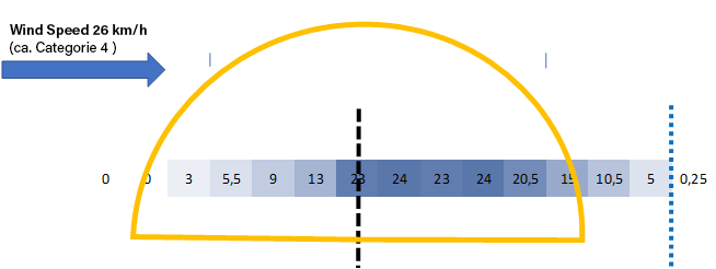
Almost no water makes it outside when it's windy. Even if the stops were adjusted to throw more water in that direction, it would make no difference (0 multiplied by 2 is still 0).
In the centre, however, instead of 23 mm, we would have significantly more.
Thus, there's nothing we can do against the wind.
On the side facing away from the wind, we irrigate approx. 10 m - 15 m outside the field boundary.
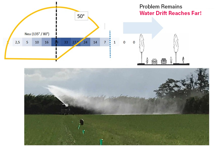
So we moved the stop on the opposite side to 50°. This is what the measurement results look like:

As already mentioned above: there is nothing you can do against the wind.
On the side facing away from the wind, it is possible to keep the water in the irrigation run - it is not irrigated onto the neighbouring run.
With Raindancer sector control, stops can be adjusted, for example, for four hours. The farmer must personally determine the time, angle, and duration of these adjustments.
Deciding whether to turn off the irrigation and restart it when the wind is weaker depends not only on water distribution but also on technological considerations: for instance, if I halt the irrigation for four hours, will I still be able to cover the fields with the available hose reels?
Therefore, if the drift crosses a road, problems are inevitable.
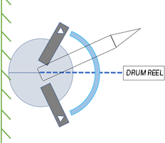
Start and End Program
Scenario: The wind is blowing from the field towards the field border,
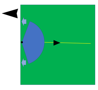
If the irrigation gun is at the beginning of its cycle, the Raindancer's throw range has little to no effect on the pivot point, causing potential drift outside the field boundary.
With Raindancer sector control:
Temporarily (e.g., for 10 minutes), the automatic sector control is switched off, and the stops are set as illustrated in the sketch.
The water will be directed towards the border, but it will not significantly cross the border.
Subsequently, you can resume using the Auto:ON mode with the throw distance as initially described.
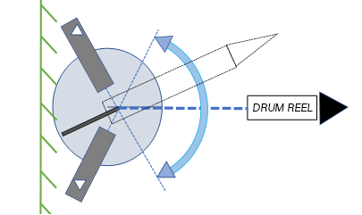
Scenario: The wind blows onto the field.
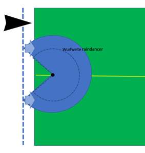 If you work with the real throwing distance, the turning point is where the water is pushed away from the border of the field and onto the field - the edge of the field itself does not get "anything".
With the raindancer sector control:
The throwing distance in the Raindancer is entered as smaller than the actual throwing distance.
The stop is thus adjusted automatically to allow turning later than "with no wind".
The water blows onto the field and water also arrives at the border of the field!
These are our (limited) measurements and our interpretations.
For scientifically based statements, far more extensive measurements and analyses are needed. However, we simply didn't have enough time for this.
We can only say here what we have measured and what our conclusions are. Please take this with a grain of salt.
Über Reaktionen, also Rückfragen, Kritiken, Anmerkungen, Ergänzungen und Diskussionen würden wir uns sehr freuen!
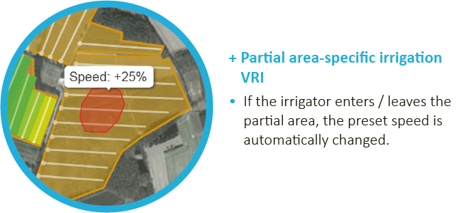
Variable Rate Irrigation - Save Water
We are all experiencing it painfully: water is becoming limited.
Increasingly, water has to be used economically when it comes to irrigation.
With varying soils in the field or dips, it can be useful to change the irrigation rate.
Raindancer makes it possible to realise area-specific irrigation.
You can draw these areas in raindancer and enter a change to the irrigation rate. If the irrigator enters/leaves this area, a corresponding IP/SMS command is sent to the hose reel.
Of course, this is only possible if your hose reel can be controlled remotely!
How it works with the raindancer
To be able to realise variable rate irrigation with the raindancer, your hose reel must of course be remotely controllable.
Within in Raindancer
Go to "Fields" in raindancer. Select the field via the "Edit field" icon on the right.
Then click on the "Coordinates" at the top.
You will now see the map of the field.
Use the "Create new shape" icon to outline the sub-area.
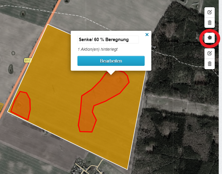
When the area is closed, you have the option of naming the event area (here: Sink / 60% irrigation) and editing it.
Click on "Edit" and then add a "New Action".
If you want to change the speed (and therefore the irrigation quantity), select :
Trigger Method: On entering
Action: Send command
Command: Change speed
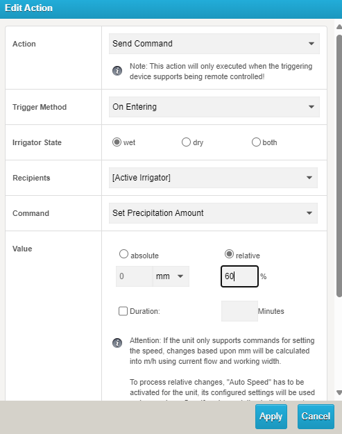 You can now select absolute (value in mm is specified) or relative - here in the example we have entered a relative change.
Example:
To reduce the irrigation rate by 40%, we choose the "relative" option.
This means that the area will receive only 60% of the previous irrigation rate, and this value (60) should be entered. If you wish to increase the irrigation (for example, by 40%), then you should enter 140%.
When the irrigator enters this area, a command is sent to the hose reel to adjust the speed.
Once the irrigator leaves the area, a command is automatically sent to the reel to revert to the original irrigation rate and speed.
We would be very glad to hear your reactions, questions, criticisms, comments, additions and discussions!
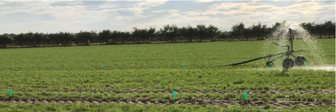
Water Distribution with Sector Control at the Start and Finish
If you work with the raindancer and sector control, you can irrigate right to the border at the start and finish.
In this film you can see how it works in action ...
To see what the water distribution looks like in reality, we took measurements of the water distribution. We placed approx. 100 measuring cups in the area in order to obtain truly useful and interpretable measurement results.
This is what the results look like:
At the start, we compare the classic irrigation with 30 min pre-irrigation with the start using sector control. Here, the gun is positioned at the border of the field and the movement starts immediately.
The stops gradually close as it moves forwards. Once the full circle has been reached, the standard setting (270° in this case) is used to continue the run.
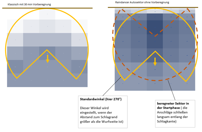
The measurement results show a significantly better distribution up to the boundaries of the field compared to the conventional method.
With conventional irrigation, approx. ¼ ha is not or barely irrigated (on average, only 25% of the planned precipitation is applied).
Let's assume, one application per day and an irrigation cycle of 8 days. This corresponds to a gain in irrigated area of approx. 2 ha per hose reel! Just at the start of the run.
We have also taken initial measurements for the water distribution at the end of the irrigation run - here are the results.
Basically, you have the option in the raindancer to set the irrigator with sector control to automatically switch to full-circle irrigation (e.g.) 60 m before the hose reel. This means that irrigation is also provided in front of; around and behind the hose reel. The full circle opens when the throw distance comes close to the edge of the field.
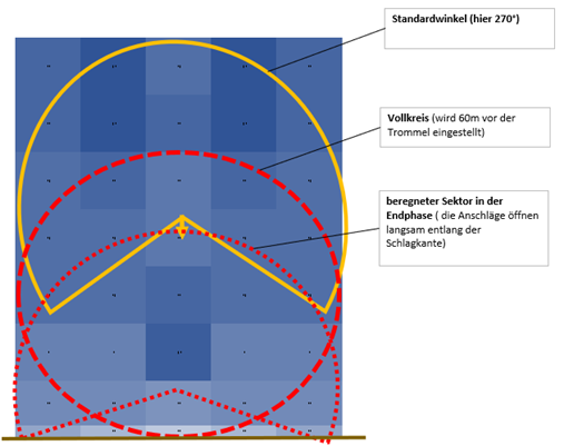
Effective water distribution is achieved here.
When the hose reel is positioned in the field before the headland, it continues to irrigate in a full circle up to the field's border. However, depending on the throw distance, there may be smaller, unirrigated areas left in the corners to the left and right.
At both the beginning and end of the irrigation run, you might notice smaller patches at the field's edge that receive insufficient water. In these instances, you can extend these areas beyond the field's boundary to ensure optimal irrigation right up to the field's edge.
How is this accomplished? By either reducing the throw distance or by marking an area outside the field and setting the status to "Allow irrigation."
Naturally, it is important to consider if there is a field path or a highway along the field's border.
Preliminary measurements for water distribution in self-propelled machines, such as in corners, have been conducted, but we are currently still evaluating. We will provide updates once we have conclusive results.
Setup Sector Control with a boom on a Fasterholt
To activate the Boomswitch in the Raindancer App, you need to go to extended settings and activate output channel two.
In default these settings are disabled. so you need to disable default checkbox and activate the features.
- has expansion ouput: active
- Output-Expansion Used Channels: Just output 2
- Output-Expansion Channel 2 Label: Boom (or similar (just the label)
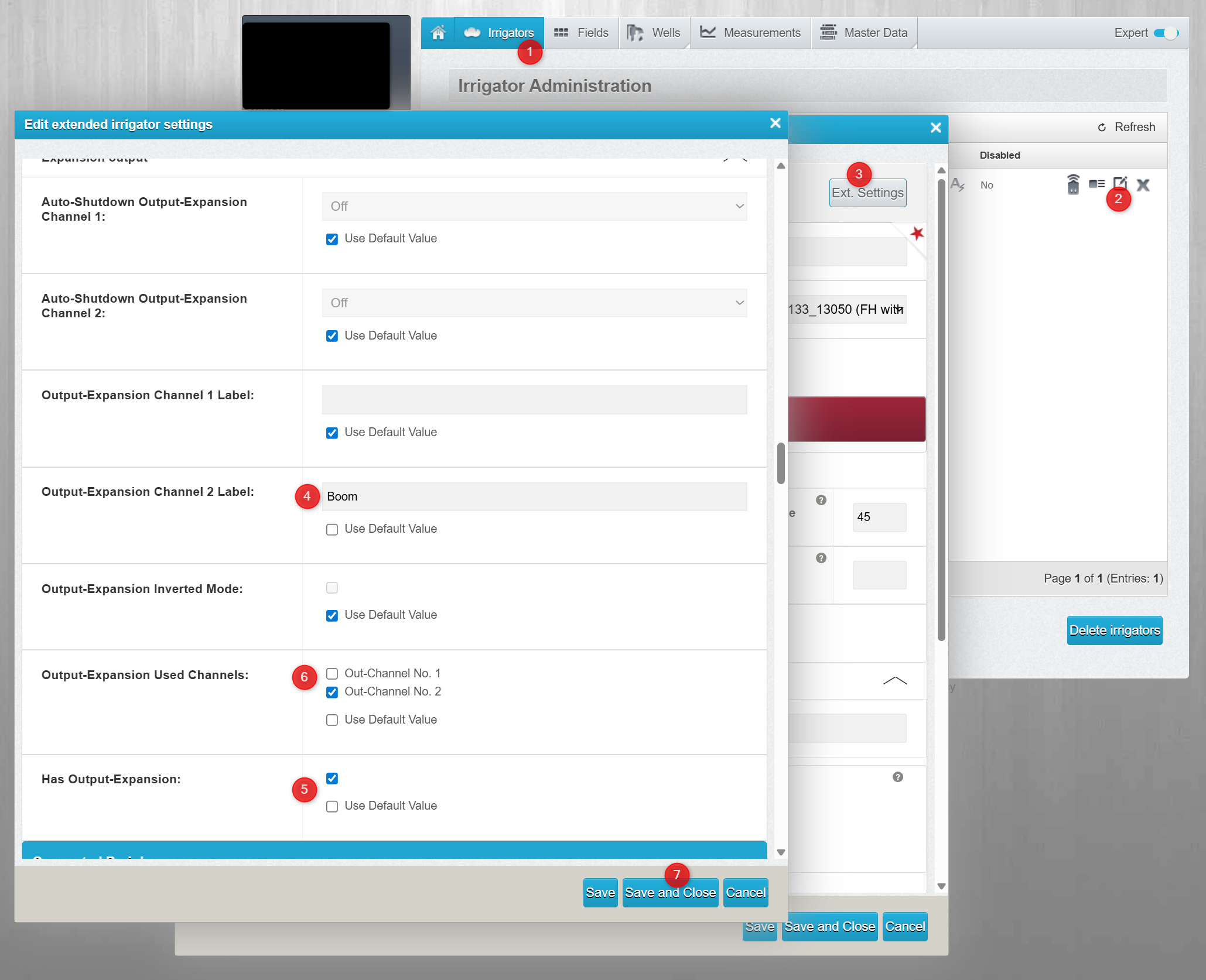
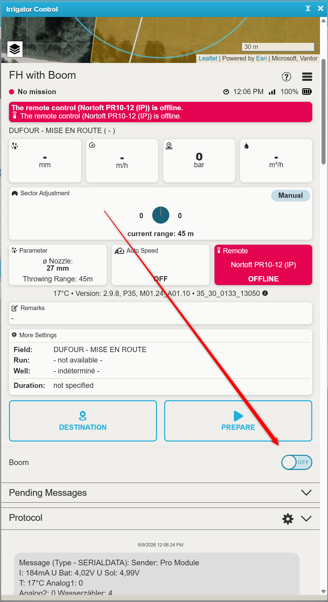
After activating the inpunt, the Output switch will be visible in control mask.
The Raindancer Beacon
The Raindancer Beacon changes the monitoring and control of pump stations, enabling real-time remote management through a web portal or smartphone app, even for those stations where this was not feasible or only possible via SMS before.
The Pump in Raindancer
This section guides you through the most important settings and configurations of the Beacon.
Settings
The settings for the Beacon are quite extensive and complex. In most cases, the relevant settings for the initial setup of the Beacon revolve around the analogue inputs and outputs as well as the error codes and the corresponding messages.
Analogue Connections
Value Ranges
The analogue inputs and outputs each have an operating mode and a value range. These two values indicate how the signal is output or expected and in which ranges the measured values fall. The scaling is linear.
EXAMPLE
A pressure adjustment is made via a 0-10 V signal.
The saved value range of 0 to 16 bar results in an output signal of 5 V when selecting a target pressure of
8 bar.
Outputs
With the two analogue outputs, you are free to choose what you want to use them for. By default, we use them to control pressure. However, if your application deviates from the standard, you can use the user-defined option to specify a name for the input and a corresponding unit of measurement. The measuring unit is used together with the value range.
In addition to the value range and the mode, you also have the option to activate manual changing of the value via the app or the web portal.
You can also customise this option by setting a value range and a corresponding increment that is available for manual adjustment.
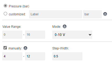
Example
In this scenario, it is possible to select a manual value between 4 and 12 bar.
The options for setting this value would each be in 0.5 bar intervals. In this example, you therefore have the option of setting the pump to 6.5 bar with a target pressure, but not to 7.2 bar or 13 bar
As you can see, you can customise your outputs here and adapt them to your individual application.
Inputs
With the four analogue inputs, you are free to choose what you want to use them for. In the standard version, we assume pressure, power, flow and rotation speed. However, if your application deviates from the standard, you can use the customised option to specify a name for the input and a corresponding unit of measurement. The unit of measurement is used together with the range of values.
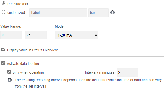
Options and visibility
This information is displayed on the details tab of your pump, accessible through both the app and the web portal. You can view this value whenever you wish.
Activating the logging options enables you to monitor the pressure values of your pump in detail and see them in the reports.
Meter Reading
The Beacon allows you to connect a digital water meter and automatically log water consumption. Alternatively, you can also use the same input to connect a rain gauge. You must select the appropriate option and enter the corresponding meter tick. The meter tick determines how many ticks are required for one litre of flow.
Please remember that if you change the mode of the analogue inputs and outputs, you must send the configuration to the Beacon for the changes to take effect.
Error Codes & Digital Inputs
You have the option of freely setting the error codes that your Beacon can display. There are 3 digital inputs available for this purpose. Depending on which inputs supply which signal, a combination of 7 different error or status messages are generated, which you can see on the app and be notified of.
The standard configuration is as shown below:
| CODE | TYPE |
Default Message |
| 0-0-1 | Error Code | Frequency Inverter / Pump |
| 0-1-0 | Error Code | Motor temperature |
| 0-1-1 | Error Code | Restart after interruption of the power supply |
| 1-0-0 | Error Code | Generic Pressure Error |
| 1-0-1 | Error Code | Exceeding Pressure Limit |
| 1-1-0 | Error Code | Pressure Limit Undercut |
| 1-1-1 | Error Code | Remote control OFF |
Digital inputs
With the digital outputs, you have the option of adjusting the pulse length according to your peripherals. By default, the beacon supplies a 125ms pulse to the corresponding outputs (1, 2, & 7) for starting and stopping as well as for the reset signal
Please keep in mind that if you change the pulse length at the digital outputs, you must send the configuration to the Beacon in order for the changes to take effect.
Technical Data
 ATSAMD21G18 Microcontroller
- 128x64 px LCD Screen with Backlight
- Membrane 3 Button Panel
- Ethernet Module (mandatory)
M2M 3G/LTE Router optionally available - Standard Input Voltage: 12V / 24V DC
permissible range: 8–28V DC
12V, 24V PSU optionally available - DIN-Rail mountable
- 4 Analog Input Channels
- 2 Analog Output Channels
- Levels: 4–20mA / 0–10V
- Fully isolated from MCU and Digital Side (1kV isolation)
- 8 Digital I/O Channels
- Digital Input Voltage Range: 0–28V
input channels internally driven LOW - Digital Output Vortage Range: 8–28V (tied to VIN)
- Digital I/O Levels: LOW ≤ 3V, HIGH ≥ 11V
I/O Logic is active high - Max. Output Current per Pin: 2.6A
(short circuit, over-current, over-temp. protected) - Max. Total Output Current: 6.5A (omni block fused)
- Fully isolated from MCU and Analog Side (1kV isolation)
- Isolated Half Duplex RS-485 Transceiver
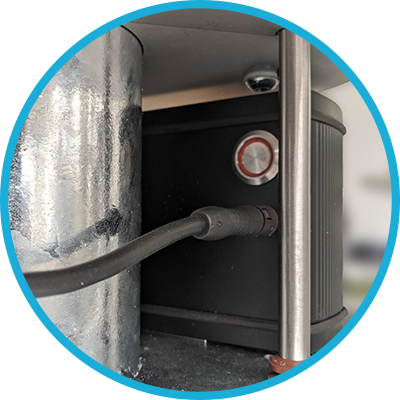
Important Notes
To properly operate the Raindancer Beacon, it has to be connected to an adequate power supply via the POWER-IN field (12/24V DC is recommended). The USB port on the front casing is not suitable.
When a single power supply is used to power both, Raindancer Beacon and peripherals, the GND lines should be tied together.
Power down all systems (Raindancer Beacon, sensors/actuators) before connecting to the Raindancer Beacon via USB, internal components may irreparably take damage otherwise!
Analog Field Section
- Analog Pins can be individually configured, according to the requirements of the devices to be connected: 0-10V or 4-20mA. By default, all Analog Pins are preconfigured to 4-20mA. An alternate configurations can be set using the web-portal.
Pin Assignment and Value Ranges when Used as Pump Control Unit:
- The value ranges can be individually adjusted using the web-portal.
| A OUT | Assignment | Default Range |
| CH 1 | Target / Min. Pressure | 0 – 16 bar |
| CH 2 | Manually Set Pressure | 0 – 16 bar |
| A IN | Assignment | Default Range |
| CH 1 | Current Pressure | 0 – 16 bar |
| CH 2 | Current Power | 0 – 100 kW |
| CH 3 | Current Flow | 0 – 100 m³/h |
| CH 4 | Current Speed | 0 – 3.600 rpm |
Digital Field Section
- Output can be configured as a permanent or pulsed signal (125ms – 256s).
Signal configuration can be adjusted using the web-portal. - Pulse counter (using level raise/fall, max. ca. 60Hz), e.g. for water meters on Digital Channel 8.
- Please note that floating/pulsing input voltages may be transmitted as highly fluctuating input signals, triggering associated actions (e.g. error notification).
Default Pin Assignment and Value Ranges When Used as Pump Control Unit:
| D CH | Assignment | Signal | Interpret. |
| 1 (OUT) | Control ON | Pulse, 125ms | ON |
| 2 (OUT) | Control OFF | Pulse, 125ms | OFF |
| 3 (IN) | Confirmation | Permanent | ON/ OFF |
| 4 (IN) | Error Code 1 | Permanent | ON/ OFF |
| 5 (IN) | Error Code 2 | Permanent | ON/ OFF |
| 6 (IN) | Error Code 3 | Permanent | ON/ OFF |
| 7 (OUT) | Reset Error | Pulse, 2s | |
| 8 (IN) | Counter | Pulse |
Error Codes
- By combining the three main Error Codes using Digital Channels 4 – 6, four additional states, up to a total of 7, can be transmitted.
- • The textual interpretations of the Error Codes can be customized individually using the web-portal.
Default Error Codes Used by Pump Control/Monitoring:
| Code 1 (CH 4) |
Code 2 (CH 5) |
Code 3 (CH 6) |
Interpretation |
| 0 | 0 | 0 | no malfunction |
| 1 | 0 | 0 | Malfunction - Pressure, generic. |
| 0 | 1 | 0 | Malfunction - Motor Temperature |
| 0 | 0 | 1 | Malfunction - Frequency Inverter / Pump |
| 1 | 1 | 0 | Malfunction - Low Pressure |
| 1 | 0 | 1 | Malfunction - Excess Pressure |
| 0 | 1 | 1 | Restart after Interruption of Power Supply |
| 1 | 1 | 1 | Remote Control Disabled |
Initial start-up of the M2M router
Optionally, the Raindancer Beacon comes with a preconfigured, ready-to-use M2M Router
(M2M – »Machine to Machine Communication«), prepared to be mounted to DIN Rails.
Overview
| Front Panel | Rear Panel |
|
|
|
| 1 Hollow Pin / Terminal Block Port Power Supply 2, 3, 4 LAN Ethernet Ports 5 WAN Ethernet Port 6 Status LED Power Supply 7, 8, 9 Status LED LAN Ports 10 Status LED WAN Port |
1 GSM Main Antenna Connector 2 Wi-Fi Antenna Connector 3 GSM Aux. Antenna Connector 4 Reset Button 5 Status LED GSM |
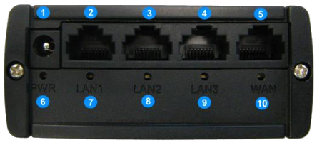
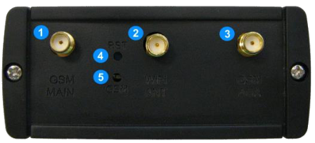
Setup
- Attach GSM Antenna to Connector [1] on the router’s rear panel.
Note: when lacking imprints, usually the GSM Antenna is the »thicker« one. - Attach Wi-Fi Antenna to Connector [2] on the router’s rear panel.
Note: by default, the preconfigured routers come with Wi-Fi deactivated, when not ordered with an alternative configuration, attaching the Wi-Fi Antenna is not required.
- Connect the Raindancer Beacon(s) via Ethernet cable to one of the ports [2], [3] or [4] on the router’s front panel.
Note: Do not connect the Beacon(s) to the WAN Ethernet Port [5]! - Connect the power Adapter to the rocket on the
router’s front panel [1].
Pay attention to polarity, when connecting to an alternative power source
(9W/9VDC min, 12V rec., 18V/30V max, depending on router model type)!
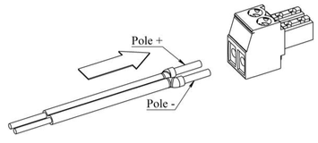
Typical Wiring Variants
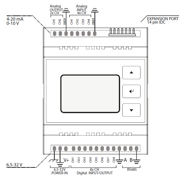
|
|
Connecting an analog sensor (AIN field) or analog actuator (AOUT field) in series
Typical application: |
||||||||
|
|
Connecting an analog sensor (AIN field) or analog actuator (AOUT field), using an external power
|
||||||||
|
|
Connecting an analog sensor (AIN field) or analog actuator (AOUT field), supplied by the same PSU.
Example:
Hinweis:
Hinweis: |
||||||||
|
|
Typical connection of a control unit using a pulsed signal (active high, pulse width configurable) for Start (CH1) and Stop (CH2).
Feedback of the operational state via permanent signal (active high) via input CH3.
Create a common ground reference when using a separate power supply by connecting the GND terminal of the digital field.
|
||||||||
|
|
Typical connection of a control unit using a permanent signal (optionally configurable) on output
|
||||||||
|
|
Example adaptation to a control unit using a permanent signal (active low) via a NC switch at CH1.
|
||||||||
|
|
Example adaptation for driving an NC switch to pull an active output low in order to stop the connected control.
The active output may be used as a feedback of the operational state.
Create a common ground reference when using a separate power supply by connecting the GND terminal of the digital field.
|
||||||||
|
|
Typical connection of a counter at input CH8. The depicted example uses a simple Reed contact.
Alternatively, any kind of impulse generator can be connected to CH8 (input active high).
The impulse frequency has to be selected according to the desired application. |
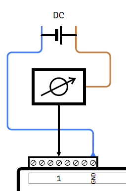
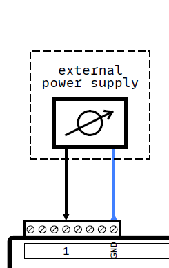
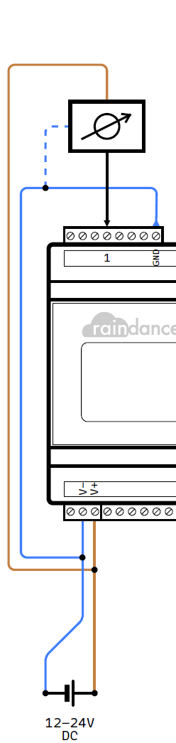
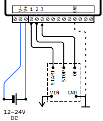
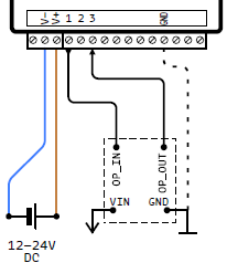
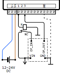
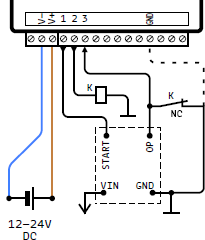
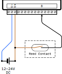
Calibration of Analogue Inputs and Outputs
Ideally, there is a direct, linear connection between the value of an analogue input or output of the Beacon and the corresponding value range of the connected sensor or actuator defined in the pump settings.
Using the example of a simple 0-16 bar pressure sensor on an analogue input of the Beacon, 0 bar measured in voltage mode corresponds to a signal value of 0 volts, 16 bar to a signal value of 10 volts and the range in between is directly proportional (i.e. 2.5V = 4 bar, 5V = 8 bar, 7.5V = 12 bar, etc.).
In reality, however, there is often a deviation, very often not only by an invariable amount over the entire measuring range, but with different magnitudes at the two ends of the range to be measured. For this reason, it may be necessary to calibrate an input/output.
Calibration can be achieved by adjusting the value range on which the signal of an analogue input or output is interpreted accordingly.
Two measurements (with a multimeter, for example) at points as far apart as possible in the entire value range are required to adjust the value range to reality in a meaningful way.
Example Pressure sensor 0-16 bar / 0-10 V:
Original setting in the portal:
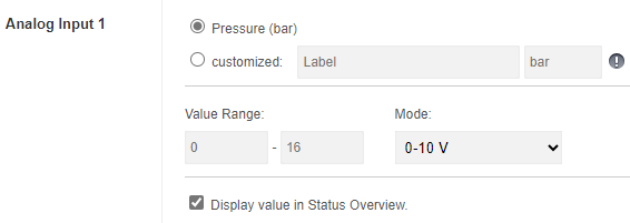
Measurement of the transmitted values and corresponding sensor values:
|
|
|
|
In the next step, these empirically determined values must be inserted into the following formula and calculated for each measured value of 0 and 10 volts:
Measured Value - Min. Measured Value.
Sensor Value = ————————————————————————————————————————————————————————————————————————————————— + Min. Sensor Value
(Max. Measured Value - Min. Measured Value) × (Max. Sensor Value - Min. Sensor Value)The results of this calculation, from -2.04 bar for measured value = 0V or 16.64 bar for measured value = 10V, give the calibrated value range to be defined for the analogue input or output:
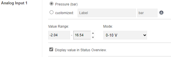
If this measurement/calibration relates to an analogue output, crooked (or simply nonsensical for the control system) values can be avoided in the manual selection by restricting the available value range using the new function. In the example case described, this would be 0 to 16 bar, alternatively further restricted to a range of 3 to 6 bar, for example, which can only actually be used:
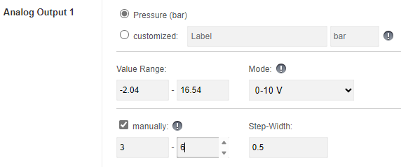
Operation Mode »Mirror Image«
A combination of two or more Raindancer Beacons can optionally be used to reflect another device to be remotely monitored and controlled. Using this method, all signals coming from or going a Beacon will be available to a »Mirror« Beacon, via a »virtual cable extension«. Periphery connected to the »Mirror« (e.g. a PLC) can retrieve this information, process it and control the remotely
controlled device via commands sent from this »Mirror« to its actual counterpart.
The number of devices configured as »Mirror« are practically unlimited.
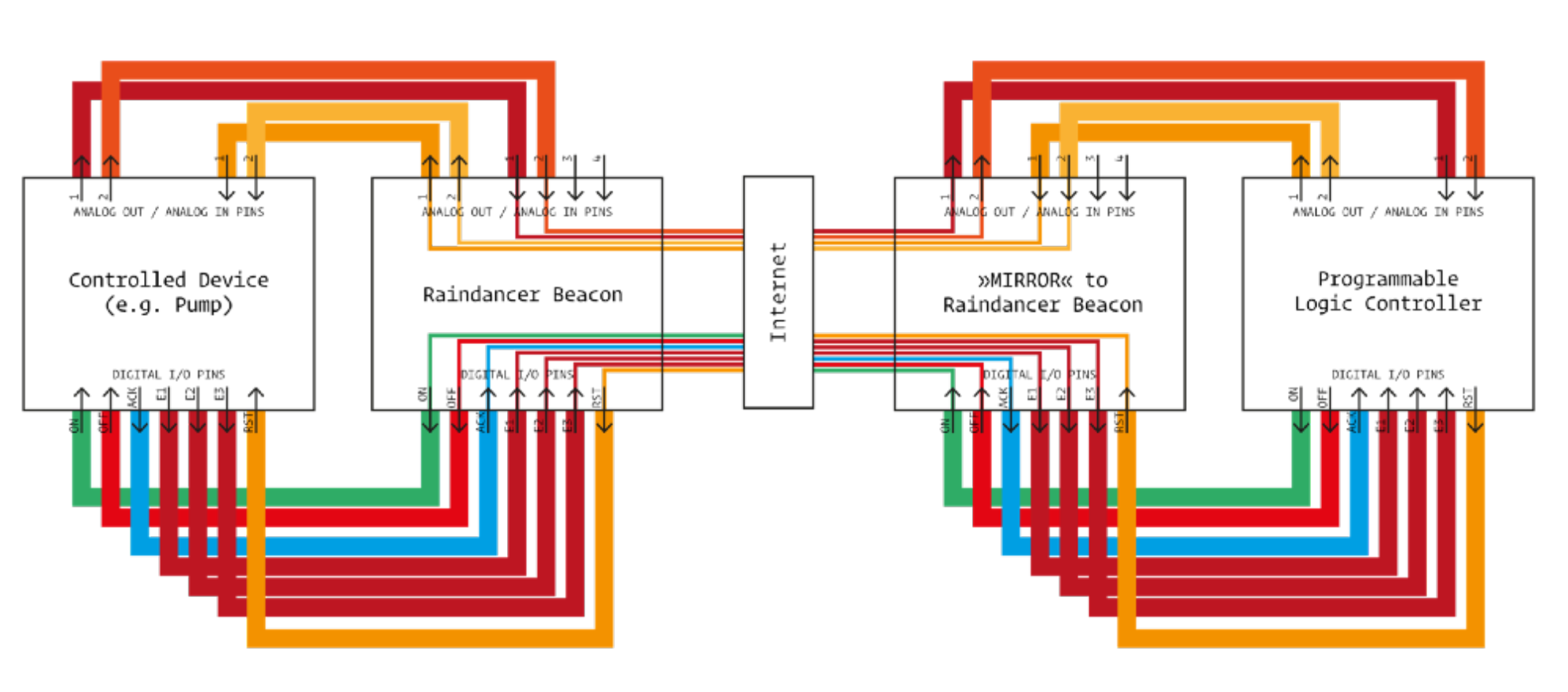
In order for a Beacon to be able to function as a »Mirror Image«, it has to undergo proper preparation, using a special configuration.
Troubleshooting in Raindancer
Here you will find simple answers to the most common problems and difficulties when using Raindancer
Replace motorbox base plate assembly
In these guide, we will take you through the necessary steps to replace the base plate including the motors.
This is only necessary if your motors are faulty and you have been sent a replacement kit.
The removal of the box is identical:
Removing the motor box
Removing the base plate
- Loosen the 4 screws on the base plate. (Torx T-10)
- Carefully remove the base plate.
- Disconnect the cable connection of the motors to the plugs inside the box.
To release the connection, carefully press in a clip on the plug connection.
It is best to use a slim flat-head screwdriver to press the clip down.
This step can be fiddly. Take your time.

-
Place the new base plate and align the plate so that the cables inside the box are on the same side as the cables on the motors and plug in the connectors.
-
Now insert the base plate all the way
-
Switch on the motor box to check that both motors are turning. Listen out for any grinding noises from the tops on the motor shafts.
-
-
Now screw the base plate back into place using the appropriate screws.
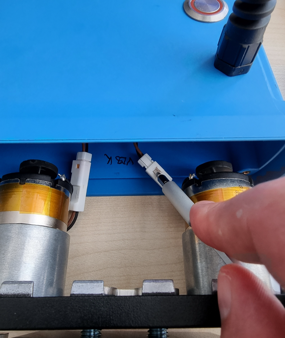
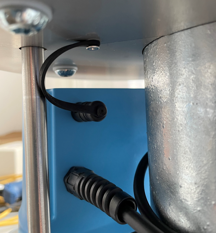 For the subsequent installation, follow the instructions for installing the motor box correctly from here
Do NOT Forget Your Cap
After installing the motor box, make sure to put the protective cap on the extension connection
Check whether the sector control is executing the commands you send from the app correctly.
Install the Motor Box Correctly
In this guide, we will explain the steps you need to take to repair your motorbox.
Mounting Details
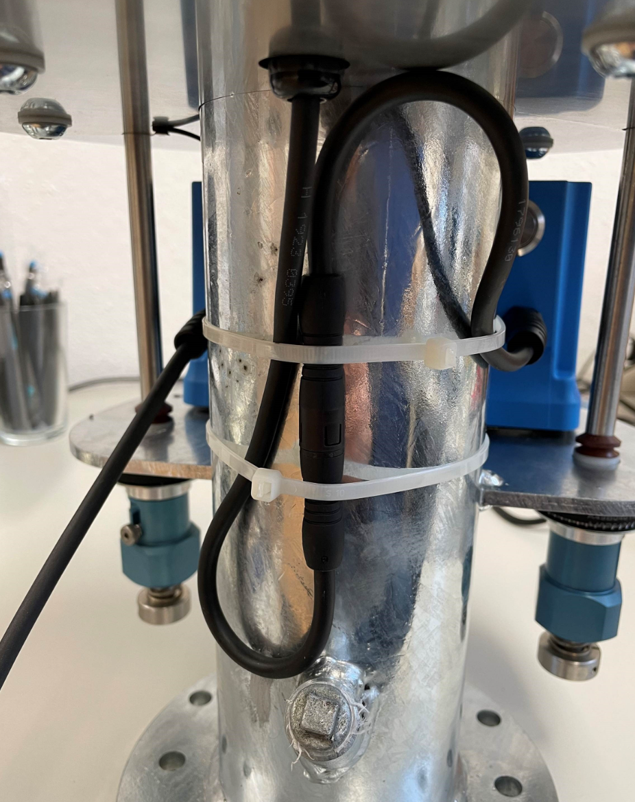
The position of the connectors on the 2021 sector controls has been changed for the sake of ongoing optimisation.
However, motor boxes of the 2021 generation are still compatible with the sector controls from the previous year.
Only the cable connection appears unnecessarily long due to this change and requires fixing as shown in the following picture.
Please ensure that the cable is laid without kinks in a loose "S" Shape and fix it with the cable ties supplied at the point shown in the photo to prevent the plug connection from becoming entangled.
Nullpunkt
If a zero point has been set for this sector control, this may not yet be known to the new motor box. If the sector control is switched on and the Raindancer module is connected and loaded, the software will automatically attempt to assign this value to the new box.
Nevertheless, we ask you to check the correct alignment of the sector control before using it for the first time.
Guide

Insert the new box into the designated cut-outs. The cables must point towards the tube and be routed between the tube and the drive shaft.
-
Make sure to mount the spacer plate on the motor box above the mounting plate of the sector control. This plate ensures the correct distance to the mounting plate.
If you have not placed the spacer plate between the motor box and the frame, the motor box may be warped and the belt drive may not be able to work properly.
 Place the belts over the belt pulleys of the shaft and the motor.
 - Tension the belt with one hand by pushing the motor box forwards and tightening the nuts under tension. The belts should be tight, but not so tight that they can no longer be squeezed in and must not be allowed to skip.
- Fit the belt caps over the belts and belt pulleys.
- Connect the short cable to the stop sensor and (for sector controls from 2020) lay it in a loose S on the riser tube and secure it with the cable ties provided.
- Caution: Do not forget to put the cover cap on the upper extension socket.
- Switch on the motor box at the on/off switch and check that both stops are moving. After a short time, the stops should stop and return to their original position.
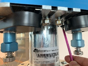
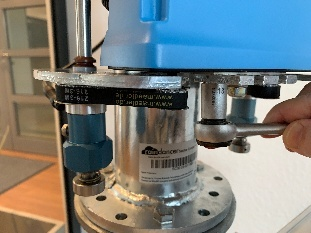
Please do not forget to engage the couplings on the bottom side.
Troubleshooting the Beacon
Compatibility check:
-
- Beacons are immediately ready for use on the Ethernet module (in combination with a router with active DHCP).
- There is a known incompatibility with certain versions of the Ethernet module
(specifically: Rev.4.2, labelled accordingly on the board).
In this case, the automatic detection and configuration of the Ethernet module fails
(see "Troubleshooting" point 2.a.i.)
- There is a known incompatibility with certain versions of the Ethernet module
- Beacons are immediately ready for use on the Ethernet module (in combination with a router with active DHCP).
- Beacons specially preconfigured for operation with the GSM/GPRS modem cannot be used with the Ethernet module1.
- To establish a data connection, corresponding access data is stored in the configuration, which depends on the respective network operator/provider. When changing the SIM card, this must be taken into account and adjusted if necessary.
Notes:
1) This would require the configuration stored in the beacon's internal memory to be adapted again; only possible via a serial direct connection to the beacon via USB.
Troubleshooting
-
Wiring / connections OK?
-
Beacon is connected to external power supply?
No power supply for Ethernet module or GSM/GPRS modem via USB! -
For combination of Ethernet module and router:
-
Ethernet module and router connected via Ethernet cable?
-
Is the correct port on the router being used?
If there are several ports, connect to sockets labelled "LAN" if possible.
("WAN" port can usually be used as an additional "LAN" port on routers set up by us) -
Check the connectivity of the router!
-
Check the signal strength LEDs on the front of the router.
-
Antenna(s) connected?
If there are several "mobile" antenna connections, connect all antennas correctly!
If necessary, use wired antennas and select a more suitable location! -
If possible, establish a connection via Ethernet cable and check the router administration.
-
Try to access http://192.168.1.1. The router's status page should show the connection status
-
It should be possible to call up a website, e.g. www.google.de. If so, it is most likely not due to the router and its configuration.
-
If necessary, log into the admin interface and check the configuration
-
-
SIM card activated?
- Check connection between Beacon and Ethernet module or GSM/GPRS modem.
If necessary, replace the PCB connector / ribbon cable. - Under certain circumstances, strong electromagnetic interference in the environment can cause interference to the wireless signal or incorrect states in the memory / program sequence (beacon and router / modem).
In such situations, ensure sufficient shielding, use external wired antennas if necessary and place them at a sufficient distance.
-
-
-
- Is the Beacon (still) running??
- What is displayed on the screen?
The bottom text line specifies the last status
- "writing FRAM" (since v2.2.0 "Search Ethernet" / "No Ethernet") There is a problem with the Ethernet module.
A brand-new Beacon arrives without a configuration and attempts to create a default configuration for the Ethernet module when it is started for the first time. The beacon attempts to address a part (the FRAM chip) that is only present on the Ethernet module; if this is found and functions correctly, the beacon configures itself for operating with the Ethernet module.
In rare combinations (so far only recorded: Ethernet module of revision 4.2 in combination with older Beacon serial numbers), this component cannot be addressed correctly. The Ethernet module must be replaced, e.g. with one from revision 5.0. Unfortunately, the revision number is only visible on the circuit board of the Ethernet module (remove the housing cover). - "Not Configured" or "Config faulty" There is a problem with the configuration of the Beacon.
With older firmware versions (1.x), the configuration is stored on an external SD card (placed in the Ethernet module or the GSM/GPRS modem). In the past, oxidation on the contacts of the SD card slot could lead to problems when reading. Carefully remove the SD card (push in carefully, the card will pop out a little), degrease the contacts and push it back into the card slot.
Newer firmware versions (from 2.0) store the configuration in the internal EEPROM, separately from the device identification. As long as the device identification can be read, at least one basic configuration (contact to the live system, analogue inputs and outputs in 4-20mA current loop mode) can always be reverted to. The service life of the internal EEPROM is limited in terms of maximum write cycles (100,000e times). - »Not Connected« The beacon cannot establish a connection to the server (see 1.)
Other possible status messages that indicate an unsuccessful connection to the server are: "Conn. Failed", "Timed Out", "Invalid Server", "Truncated", "Invalid Resp.", "Domain Not Found" or "Connect. Error" indicate that a network connection could be established, but problems occurred when contacting the Raindancer servers. In addition to the steps under point 1 (in particular 1.iii.3, you should try to access the Raindancer web portal at https://portal.myraindancer.com/ via a direct connection to the router). - »Send Status« the current status of the inputs and outputs is or has been transmitted to the server.
This is the usual state.
- "writing FRAM" (since v2.2.0 "Search Ethernet" / "No Ethernet") There is a problem with the Ethernet module.
-
Can the backlight / menu be activated by pressing the buttons on the display?
If this fails repeatedly and the status indicator on the display does not change over a longer period of time, this indicates a programme crash.
Note: in certain phases of the programme (e.g. when establishing a connection via GSM/GPRS modem), the beacon does not appear reactively, repeat the test by pressing a button after some time.-
Firmware versions < 0.7.1 should possibly be updated (device replacement).
There was a problem with the 1286 variants when renewing DHCP leases, which could cause the Beacon to crash. -
Firmware versions < 1.2.2 should be reconfigured to static IP.
There was a problem with the D21G variants with considerable memory fragmentation when requesting DHCP leases. -
Firmware versions < 1.1.1. may have problems with serial communication via RS-485 interface.
-
Firmware versions ≥ 0.7 with programme crashes are not yet known; if necessary, check EMC (electromagnetic compatibility) / environment for interference.
-
Under certain circumstances, strong electromagnetic interference in the environment may cause faulty states in the memory / programme sequence.
In such cases, sufficient shielding should be ensured.
-
- What is displayed on the screen?
- Overview of Beacon variants and firmware versions:
- D21G - current hardware variant, firmware versions ≥ 1.1.0
- Firmware version ≥ 2.0.1 sends additional debug information after reconnection (uptime, free memory, frequency of the main loop).
- Firmware version ≥ 2.0.0 supports a remote restart and is handled accordingly in the configuration interface.
- Firmware versions < 1.2.2 should be configured to static IP, as there was a problem with significant memory fragmentation when requesting DHCP leases.
- Firmware version ≥ 2.0.1 sends additional debug information after reconnection (uptime, free memory, frequency of the main loop).
- 1286 - EOL, firmware versions ≤ 1.2.2
- Firmware version 0.7.2 is identical to version 1.0.0.
- Firmware version ≥ 0.7.2 can be reconfigured remotely to static IP.
- Firmware versions < 0.7.1 should possibly be updated (device replacement)?
There was a problem when renewing DHCP leases, which could cause the Beacon to crash.
- Firmware version 0.7.2 is identical to version 1.0.0.
- D21G - current hardware variant, firmware versions ≥ 1.1.0
The Beacon in Pivot Irrigation Systems
"Message without payload" - The beacon does not send any data via the serial connection
It could be that the internal physical switch is not set correctly. The switch is located inside the Beacon.
The switch should be set towards the 14-pin connector to enable serial communication via RS-232.
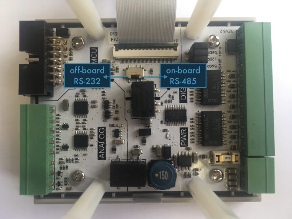
Remove the Motor Box Gasket
This section explains how to remove the gasket between the base plate and the blue box cap.
It is possible that the electronics of the motor box do not correctly detect the revolutions of the motors, which either leads to a blocked stop error message or to the sector control occasionally controlling slightly incorrect angles.
Toolkit
- Allan Key 3 mm
- Wrench 13 mm
-
TORX 10
Dismounting the Motor Box
The motor box is dismounted in exactly the reverse order to installation. [Install the Motor Box Correctly]
-
Switch off the motor box.
-
Use the Allen key to loosen the two screws on the caps above the belts.
-
Use a 13 mm open-end wrench or a ratchet with a suitable socket to remove the two central nuts
underneath the motor box. -
Remove the belts from the belt pulleys.
-
Disconnect the cable that runs from the motor box to the sensor above it.
-
Remove the blind cap on the back of the motor box.
-
You can now pull the motor box forwards out of the guides.
Should I Remove the Gasket?
The motor box can be opened by removing the 4 TORX-10 screws.
To decide whether removing the seal is the solution for you, look at the magnetic discs on the motors.
If your motors are equipped with smaller magnetic discs, it may help to remove the rubber gasket.
Removing the gasket allows the base plate to come around 2 mm closer to the sensors in the cover of the motor box, so that the revolutions of the motor can be counted correctly again.
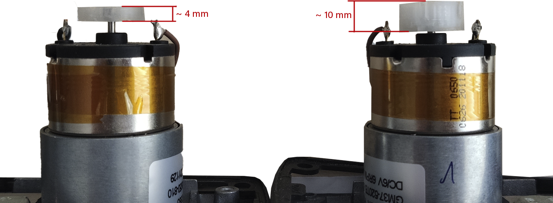
You can simply pull the gasket down over the base plate without having to disconnect the motor cables.
If your base plate is already equipped with the bigger magnetic discs, this fix will not help and you will therefore need a base plate with new motors. Please contact our support team and we will organise the shipment of a replacement part as quickly as possible.
You can find more information on this topic here Replace motorbox base plate assembly
Installing the Motor Box
To install the motor box, please follow these instructions.
-
Insert the motor box with the spacer plate directly pressed on the base plate of the motor box in the mounting.
-
Slip on the belt.
-
Tension the belt by pulling the motor box forwards.
-
Make sure that you tighten the belts, but neither too tightly nor so that the belts can skip.
Ideally, you can still squeeze the belt together a little -
Tighten the nuts under the motor box one after the other under tension.
-
Now plug the cable from the motor box into the upper sensor.
-
Set the stops to a +90/-90 position (semi-circle) and switch on the motor box.
-
Switch on the motor box.
-
After successful adjustment, you can refit the belt cover
-
Do not forget the blind cap on the back.
WhatsApp Notifications are not Working.
If you do not receive any notifications via WhatsApp, this may be because WhatsApp has not authorised your telephone number to communicate with business accounts. Unfortunately, we can't automatically check the WhatsApp messages reaching you.
In case you are not sure if your phone number is activated, please follow one of the two approaches:
Option 1: Confirmation of the policies via WhatsApp
Click here
OR
-
Create a new contact called "Raindancer Support" on your mobile phone. The service telephone number is:
+49 30 89 00 61 70. -
Open WhatsApp and search for the contact you created, "Raindancer Support".
-
Send a message with the text: "WhatsApp confirmation" to this contact.
-
A new WhatsApp window will appear asking whether you like to approve communication with business accounts. Please confirm this message.
-
You are welcome to test the correctness with the test send function in the user settings
Option 2: Switch to Text Message or e-mail
-
Select the desired communication channel (SMS or e-mail).
-
If you choose SMS, please remember to confirm the costs and tick the appropriate box.
-
Send yourself a test message to make sure that there are no transposed numbers in the telephone number or spelling mistakes in the e-mail address.
Troubleshooting the Sector Control
The following assistance applies to sector firmware version 36 and newer. For older versions, errors may have different causes.
Ensure that your Raindancer sector control is switched on and connected to a transmitting Raindancer module.
All error messages from the sector control should be taken seriously!
If the position of the stops cannot be determined accurately, the display on the smartphone may be incorrect and calculations can be wrong.
Error List
The sector control distinguishes between four different errors. We will go through each one and show you potential countermeasures to prevent further damage.
1. Turned Off or Connection Lost
This error indicates that the Raindancer panel and the motor box of the sector control cannot establish a connection. In most cases, this is because the sector control is switched off or a cable connection is defective or loose.
On older software versions, it may also be due to a wrong configuration. After checking cables and the switch, we recommend performing a firmware update (version P32 or higher) to rule out this cause.
What You Must Do:
-
Check the cable connection between the Raindancer GPS module and the motor box for:
-
Proper seating
-
Bent or damaged pins
-
Water or corrosion damage
-
-
Make sure the sector control is switched on.
-
Ensure that your Raindancer module is already connected to the Raindancer cloud and is sufficiently charged.
If you still cannot establish contact with the sector control, please contact customer support to discuss the next step
2. Stop Blocked
This error message means that one or both stops cannot move as intended. In this case, first check the moveablility of the sector control.
Steps for Checking:
-
Decouple the stops Release the blue couplings at the lower end of the sector control to decouple the stops.
-
Manual Inspection of the Stops
-
Turn each stop by hand a full 360°—this should be possible without significant force.
-
Check for any grippy spots.
-
If a stop is unusually grippy, the sector should be cleaned or serviced (an instructional video is available).
-
-
Check Behavior on Start-Up
-
Switch on the sector control using the rear switch.
-
Expected Behavior:
-
Both motors move.
-
If the stops are coupled, the arms move about 20 degrees and then return to the starting position.
-
-
-
Possible Causes of Motor Non-Movement:
-
Defective Motor: If only one motor remains still, that motor is likely defective.
-
Power Supply: If both motors do not respond, the sector control may lack sufficient power.
-
Check whether the connected Raindancer GPS module is functioning and has had enough sunlight to charge sufficiently to power the sector control .
-
-
If the above checks do not resolve the issue, customer support may be able to help via configuration adjustments.
-
-
Sensor Malfunction If both motors work normally but the message “Stop Blocked” still appears, there is likely an issue with the sensors on the motors.
When to Contact Support: If the error persists, please reach out to customer support.
Quick Self-Help for Older Sector Control
Follow our instructions for removing the motor box gasket.
In Short:
-
Check free movement in the decoupled state.
-
If the sector is stiff, wait and perform maintenance.
-
If only one motor turns or the error persists during movement:
-
Possibly remove the seal.
-
Inform support.
-
-
If both motors do not turn:
-
Ensure power supply.
-
Check cables.
-
Inspect the Raindancer GPS module.
-
Allow enough time for charging.
-
-
If both motors do turn:
-
Sensor issue likely.
-
-
If the problem continues, please contact us.
3. Stop Angle Unknown
This error message means that the sector control cannot determine its exact position. Although a blocked motor could also cause this (in which case both error messages would appear), the usual cause is a fault in the upper sensor.
Key Points:
-
Position detection is not based solely on the motor but also on a sensor located between the upper rings.
-
For this sensor to work correctly, the cable connection from the motor box to the upper sensor must be flawless.
What You Must Do:
-
Check Cable Connection Inspect the connector between the motor box and the upper sensor:
-
Are all pins present and undamaged?
-
Does the connector sit firmly and without wiggle?
-
Is the connector housing intact (no cracks or breaks)?
-
-
Exclude Prior Errors Ensure that the error message “Stop Blocked” has already been resolved (see the corresponding section above).
When to Contact Support: If the error persists after checking the cable connection and ruling out a blocked stop, please contact customer support to discuss the next steps.
4. Stop Decoupled
This error message indicates two possible problems:
-
Physical Decoupling of the Shaft The shafts are connected to the motors via the blue couplings at the lower end. In the coupled state, it should be impossible to move the stops by hand.
-
Same Cause as “Stop Angle Unknown” If no physical decoupling is present, the error can have the same cause as “Stop Angle Unknown” (e.g., sensor or cable issues).
What You Must Do:
-
Check If the Stops Are Truly Decoupled
-
Release the blue couplings to separate the shaft from the motor movement.
-
Turn the stops by hand:
-
Do they now move freely?
-
If yes, physical decoupling is normal.
-
-
In the coupled state, the stops should not turn by hand. If they do, check the following points.
-
-
Inspect These Points if the Stops Are Unexpectedly Loose
-
Locking Screw: Is the screw on the coupling present and tightened?
-
Motor Pulley (Riemenrad):
-
Remove the belt cover and try to turn the pulley by hand.
-
The pulley must not turn by hand.
-
-
Upper Stop Pinion (Ritzel):
-
You should not be able to see or reach the pinion from the outside. If any of these components are missing or loose, the stop may be decoupled when it should not be.
-
-
-
Exclude Cause “Stop Angle Unknown” If all mechanical components are intact and the stops still cannot be located, the cause may be the same as for the error “Stop Angle Unknown.” Proceed as follows:
-
Check the cable connection from the motor box to the upper sensor (see the section "Stop Angle Unknown").
-
Ensure connectors are fully seated and pins are undamaged.
-
When to Contact Support: If the problem continues after checking the mechanical couplings and sensor wiring, please contact customer support to determine the next steps.
FAQ - Frequently asked Questions
"No registered devices for push notifications were found for this user."
Introduction
Our app sends important information via push notifications.
To ensure these messages are displayed, notification permissions must be enabled in your device’s operating system (Android or iOS).
If you tapped “Don’t Allow” when the app first asked for permission, you can enable notifications later in your device settings.
This guide shows you step by step how to do that.
Enabling Push Notifications on Android
Step-by-Step Instructions
- Open the Settings app on your Android device.
- Scroll down and tap Apps or Apps & Notifications.
- Select our app from the list.
- Tap Notifications.
- Turn on the switch for Allow notifications.
- Make sure that individual notification categories (if displayed), such as Messages, Alerts, or Updates, are also enabled.
Note
Depending on your device manufacturer (Samsung, Xiaomi, Google Pixel, etc.), menu labels may differ slightly.
The procedure, however, remains mostly the same.
Enabling Push Notifications on iOS (iPhone/iPad)
Step-by-Step Instructions
- Open the Settings app on your iPhone or iPad.
- Search and Tap Notifications.
- Scroll down and select our app from the list.
- Enable the switch Allow Notifications.
- Choose how you want the notifications to appear:
- Lock Screen
- Notification Center
- Banners
- Optional: Enable Sounds or Badges if you want audio alerts or visual indicators.
How Do I Know It’s Working?
- The message “No registered devices for push notifications were found for this user.” will no longer appear in the portal.
- After sending a test message from the user settings, you will see a new notification in the app’s notification area.
Frequently Asked Questions
Why do I have to enable this manually?
If you deny notification permission the first time the app asks, the app is not allowed to request it again.
This is a security feature of the operating system.
Is it safe?
Yes. Push notifications simply inform you about new content.
We do not access any personal data when you enable notifications.
Extended Functions of Raindancer
In this section you will learn about some of the advanced functions that your Raindancer system can offer you.
Import VRI Zones
VRI Zones
The VRI zone importer can be used to import VRI zones from a shapefile into Raindancer.VRI zones are event areas that cause irrigators to change the irrigation amount by command when the irrigator enters the zone.- Zones that adjust the irrigation amount as a percentage (Relative Percent)
- Zones that adjust the irrigation amount in millimetres (Absolute in mm)
- Zones that adjust the irrigation amount in metres per hour (Absolute in m/h)
- "Relative per cent" zones can have values between 1% and 100%
- "Absolute in mm" zones can have values between 1mm and 50mm
- "Absolute in m/h" zones can have values between 5m/h and 150m/h
Activating the VRI zone import
Requirements for shape files
Shape files that can be imported as VRI zones must have the shape type polygon or multipolygon.
They must also contain at least one data column containing the names of the zones.
The features in the shape file should all be simple polygons, i.e. features that only consist of a polygon without holes.
If a polygon feature consists of several polygons, only the first one is imported as a zone. Holes are discarded.
Import process
The VRI zone importer can be opened in Raindancer in the area section with the "Import VRI zones" button.
The mapping of VRI zones to fields is established during import by the geographical position of the polygons in the shape file. If the polygon of a zone is located on a field, it is added to this field.
Open Data
In the Importer, you can open the individual files of the shapefile using the "Select files" button. All files belonging to the shapefile must be selected in the open dialogue.
After selecting the data, start the import process using the "Check format" button.
Import Options
Projection
If no projection is included with the shapefile, the projection of the shapefile must be selected here. If an incorrect projection is selected, the VRI zones on the map may be in the wrong position or contain completely invalid coordinates.
Name
Here you select the data column of the shapefile from which the names for the VRI zones are to be obtained.
Number zone names consecutively
If the "Number zone names automatically" box is selected, the names of the zones are not taken from a column but are numbered automatically from 1 to n.
VRI zone type
Here, you select the type of zones to be imported. If no type has been selected, the import button is not displayed.
VRI zone value
You can select here whether the individual zone values should be obtained from a data column in the shape file or whether all zones should be given the same fixed value.
If you select "Load value from a file column", you can select the corresponding data column in a second selection. Only columns containing numerical values are offered here.
If one of the numerical values is outside the limits defined above, the VRI zone is not defined.
If the shape file does not contain a column consisting only of numerical values, it is only possible to import zones with a fixed value.
If you select "Fixed value for all zones", a numerical input appears in which you can define the value. The input is restricted to the limits mentioned above.
Dealing with existing VRI zones
Finally, you must define whether the existing VRI zones are to be changed. You can choose between
"Replace VRI zones on affected fields" - The VRI zones of all existing fields for which zones are contained in the shape file are deleted before the import and thus replaced by the new zones from the file.
"Do not change existing VRI zones by import" - All existing VRI zones are retained. This may result in new zones being assigned over existing zones. However, if there are no zones at the positions of the VRI zones from the shape file in Raindancer, this is the optimal variant.
"Delete all existing VRI zones before import" - Deletes all VRI zones of the client and imports the new zones from the file. This option is useful if the shapefile contains all of your client's VRI zones.
Grant or Revoke Third Party Access
When your account is created, a service account is always created which gives the Raindancer-Supoort team access to your account so that they can quickly provide assistance.
It is possible for Raindancer partners to be granted third-party access to their account. This authorisation is only for support purposes for certain products or applications.
These partners can assign or remove devices from your account and log in to your account to check the function of the devices they maintain.
Only appropriately trained partners can apply for third-party access to their account.
You always have full control and you can easily remove these authorisation at any time.
Consent for Access
To allow third-party access, you will find a Third Party Access management button in the menu item Settings ⇾ Users, if a request has previously been sent to you.
![]()
This function can also be found in the APP under More ⇾ Third Party Access
Access List
In the list that is displayed, you will see the requests at the top and any authorisations that have already been granted below.
In the requests, you can see which Raindancer partner made the request and when, and whether access was requested via a support account. Third-party access can also take place without the integration of a support user. In this case, the partner only has the option of adding or removing devices from their account.
You now have the option of confirming or refusing the request.
Revoke Access
At any time, you have the option of revoking authorisation by clicking on the cross.
Irrigation Machine - Take Control, Remotely
Select your control unit and follow the instructions.
Please understand that we have no direct control over the software version of the machine computers and that these instructions may differ slightly from those on your machine.
If you have any further questions about the machine configurations, please contact us at www.raindancer.com/contact
Beinlich 2KR
Settings in Raindancer Mode
Set-Up the Raindancer Mode
Setup the GSM Module in Parameter-Settings
Buttons for entering the Parameter-Settings: MENU + D
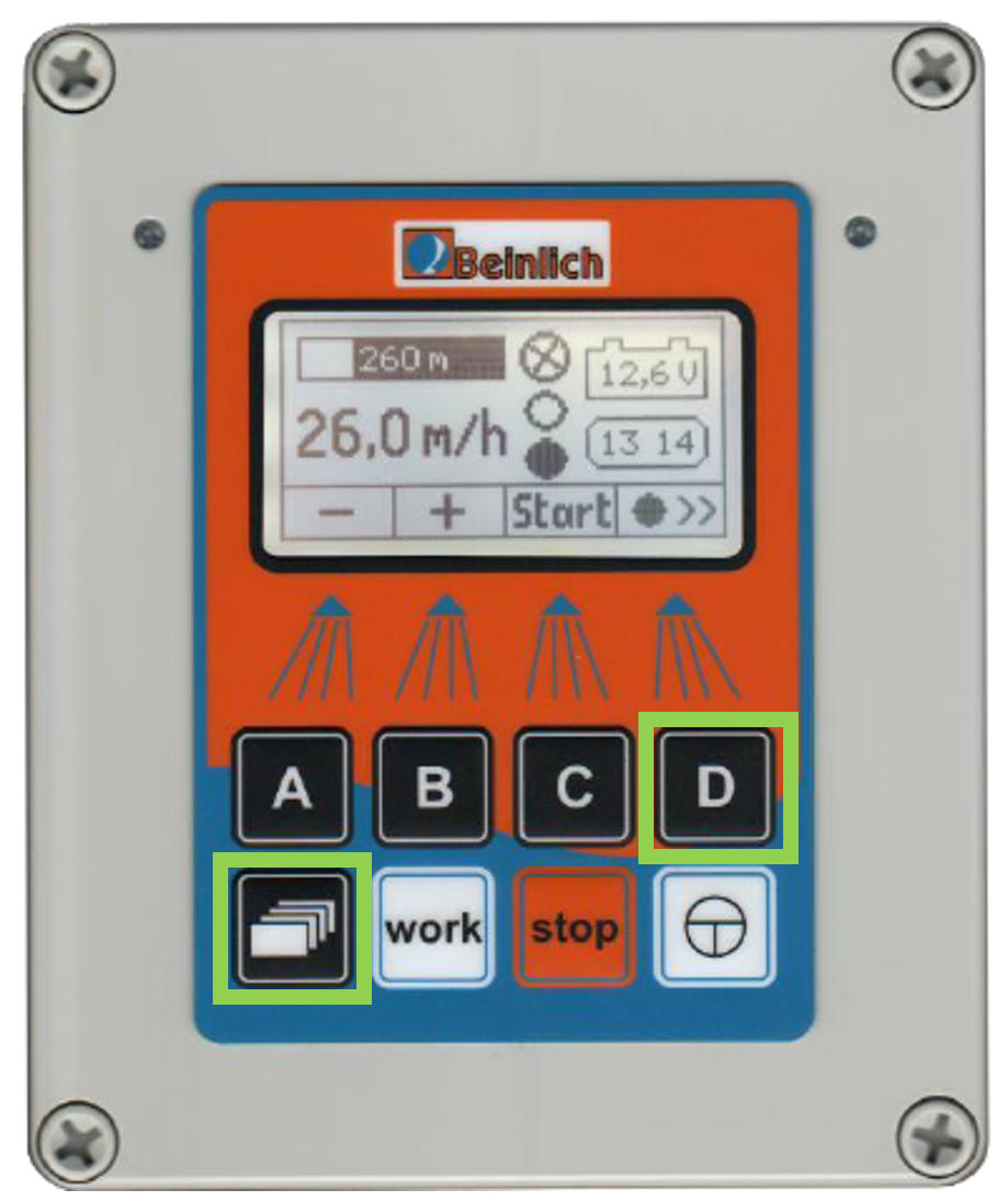
- Choose "GSM" with A/B and select with C
- Choose "Raindancer" with A/B and select with C and save with D
Setup the Raindancer-Connection in Main-Settings
- Enter Main-Settings with

- Choose "Raindancer" with A/B and select with C
- Type in Your Machine Number (freely selectable - example 001)
- At "Own" type in the SIM-Number (format: +31.....)
- At "Server" type in +4915251045215
- Confirm with D
Done!
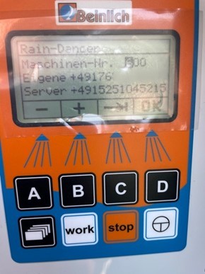
Own number:
This is the number of the SIM card that is installed in the control unit.
This number must also be stored in the Raindancer portal in order to access the machine
Server Phone Number:
| +31 970 144 449 93 |
Attention - Poor Signal Reception
The antenna connection is installed at the bottom of the box.
Elektronik_2KRH_V6.8.pdf (German)
Nortoft PR10-12
For SMS Mode
- Speed = 11,1 → Const 100.
- M.Data 30 = 1 (All phone numbers can send commands)
-
B = Enter Raindancer phone number in international format.RD-Classic Sim-Karte: +3197014444993RD-Conekkt Sim-Karte: +6260Own Sim-Karte: +4915251045215
-
M.Data 50 = 1
-
Menu Buttons → Save.
-
Check: Text Message with STATUS to the Nortoft Controller→ Status Text Message reply is expected
For Internet Usage
- Speed= 11,1 → Const 100.
- M.Data 30 = 1 (All phone numbers can send commands)
- M.Data 50 = 2
- Menu Buttons → Save.
- Check: Text Message with
("IP":"SETUP","READ":0)to the Nortoft Controller
→ Reply should contain Serial Number („SN“:)
If a telephone number is set up in Nortoft for SMS configuration, the SMS reply may be sent to this number and not to the mobile phone that sent the IP setup SMS. With IP, the SMS number can be deleted.
Detailed Instructions
Set the computer to the configuration mode:
Set Speed to 11,1 ( use Ë/¬ Buttons) and press 3 times the PROG-Button. The line with "Const 100" appears.
Step up this Value using Ë/¬ to 111 then click PROG again .
You now have access to the "M.Data" list, which you can navigate through using the PROG button.
Please note that not all M.Data numbers are available. After M.Data 24 comes M.Data 30. You cannot navigate backwards, but the list starts from the beginning after M.Data 55 [depending on the firmware version of the device].
Set the value of M.Data 30 to 1 using the Ë/¬ buttons. This activates the GSM modem. The following entries in the M.Data list are called A and B and represent two telephone numbers.
A restriction to two telephone numbers ( M.Data 30 to 2 ) is only permitted in SMS mode.
For Operation via IP
- Set the value of M.Data 50 to 2 using the Ë/¬ buttons.
- Save the entries by pressing the Menu button. This will take you out of configuration mode (M.Data list) and 'Status Power On' should appear.
- The serial number is labelled on the device and must be set as the identifier for the irrigator in the Raindancer portal.
The telephone number of the device SIM card must also be stored in the portal. As soon as the irrigator is configured and has a sufficiently good connection to the wireless network, you should be able to observe communication with the device. - To verify this, the serial number can be requested by sending a text message to the SIM card. The device sends a reply to the message
("IP": "SETUP", "READ":0), which contains the serial number ("SN":). - However, a proper function check only works if the remote control device with the serial number is assigned to the client via the client administration and an irrigator with the serial number & telephone number) has been set up. PING messages are then sent to the remote control screen every 5 minutes.
For Operation with Text Messages
- Use the Ë/¬ buttons to set the value for B after M.Data 30 to the Raindancer telephone number in the style +491520xxxx.
It is important that the entry B is used, otherwise the communication won't work.
If you have been supplied with a SIM card, use the following telephone number depending on the SIM card.
Raindancer SIM card: +3197014444993
RD-Conekkt Sim-Karte: +6260
Own SIM card: +4915251045215 - Set the value of M.Data 50 to 1 using the Ë/¬ buttons.
-
Save the entries by pressing the MENU button. This will take you out of configuration mode (M.Data list) and something should appear Status Power On.
-
If you send the STATUS command to the machine via text message the computer should send a status message to the set telephone numbers.
Setup Hüdig Control
The following settings must be made for Hüdig Controls.
- Activation of the GSM/SMS control
Save the SMS connection
Setup on the portal
Activation of the SMS control on the hose reel
A SIM card must be inserted into the machine and a configuration made on the Huedig Control. Detailed instructions can be found in Huedig Control complete (DE) on page. 25
Setting up SMS control via Text Message
Once the SIM card has been inserted and activated, control text messages can be sent to the computer.
Setting the Event Query
There is a defined pattern for this:
T 01 (Slot bis 19), Server Number (003197014444993), 9(all Events) Name
Beispiel:
T 01,003197014444993,9 RD
Setting the name of the irrigation machine in answers for easier assignment
There is a definite scheme for this:
T 20 (Slot for Name), Server Number (003197014444993), Name of Irrigator
Beispiel:
T 20,003197014444993,Irrigator 4
Checking the entered data
As soon as all settings have been made, queries can be sent to the Hüdig controller to check the respective memory data registers.
R + Number of Register
R 01
Irrigator 4:
T 01,003197014444993,9 RD
Further settings
For further settings there is the Instructions for SMS control from Hüdig
Ocmis API
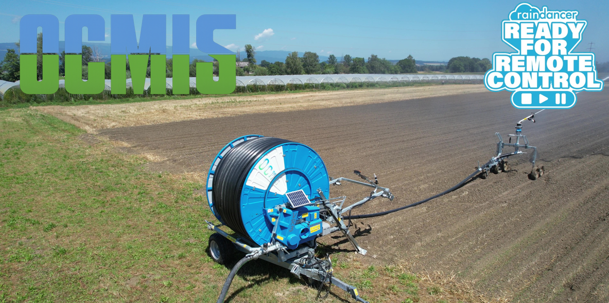
This guide applies to all IP controllers in the OCMIS product family running software version 24.0.1 or later:
Irtec Smart Rain, OCMIS RainControl 5 & Marani
1. Create a New API in the Raindancer Portal
- Configure the API connection in Raindancer under Settings → API → New API

-
API Name: Freely selectable
Example: OCMIS API -
ID: Automatically generated
-
Key: Freely selectable
Example: Raindancer2026!
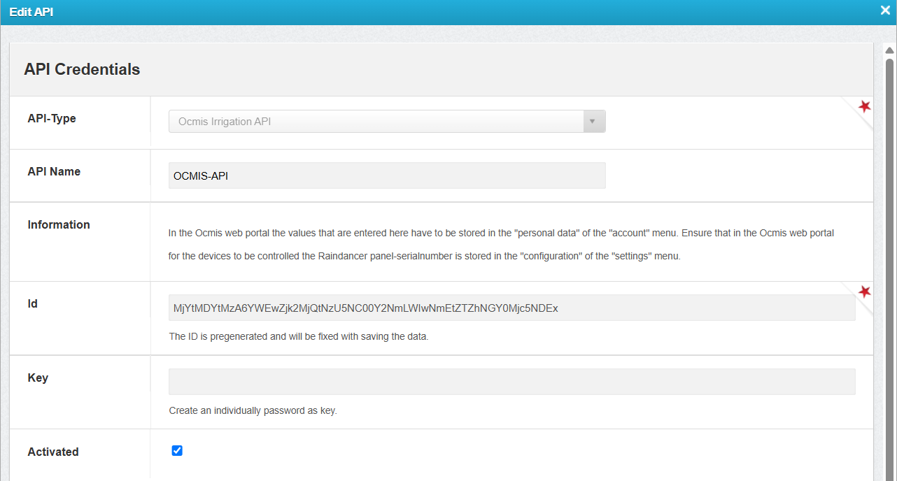
2. Configure the API and Irrigator in the OCMIS Portal
Enter the Raindancer API credentials in the OCMIS Portal.
- Log in to the OCMIS Portal (https://www.irriverso.com/)
- Navigate to "My Apps" and click "Digital Irrigation"

- Click "Account"

- Click "Edit Personal Data"

- Enter the API ID and API Key, then click Save

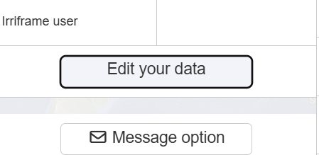
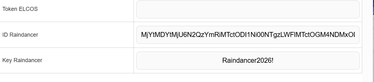
Configure the Irrigator in the OCMIS Portal
- Open the Irrigator Overview.
-
Navigate to Settings → Configurations.
- Select Raindancer Mode and enter the serial number of the Raindancer module installed on the irrigator cart for this machine.
- Save

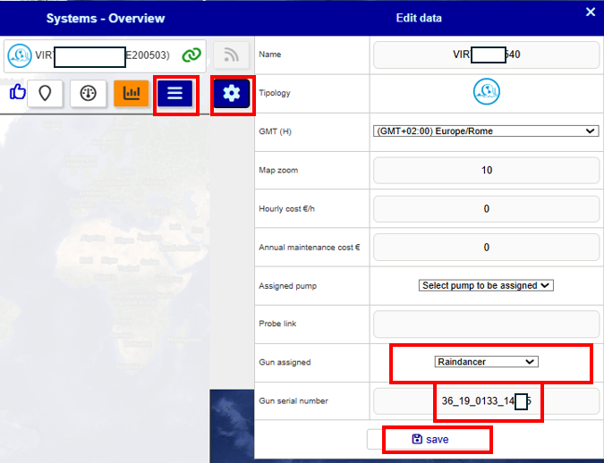
3. Assign the OCMIS Controller Serial Number in the Raindancer Portal
1 Find the Controller Serial Number
- Log in to the OCMIS Portal
- Copy the irrigator's serial number without the parentheses

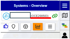
2 Assign the Controller to an Irrigator
- Log in to the Raindancer Portal.
- Open the Setup and Controller section.
- Controller Type: OCMIS API
- API Name: The API name created in Section 1.2 (Example: OCMIS API)
- Select Controller: Choose the copied serial number from Section 3.1 (Example: OCE200503)

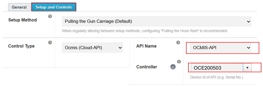
4. Set up the OCMIS control unit on the reel
For the following steps, it is necessary to familiarize yourself with the reel's user manual to avoid making incorrect settings. The manual also contains the access credentials for the various configuration menus of the OCMIS control unit.
It must also be ensured that the modem of the OCMIS control unit is active and that either a dedicated SIM card or the e-SIM of the installed router is working.
If you have any questions regarding the topics in this section, please contact your OCMIS sales partner!
Activate Raindancer mode for the irrigator trolley
-
First, enter the password ABC123 via the lock icon at the bottom left

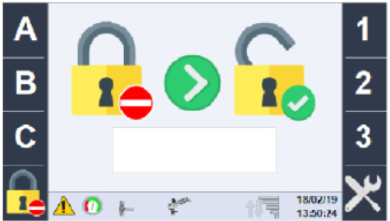
-
Now use the green arrow keys to scroll to the gun configuration, then use the rotary dial to switch to Raindancer mode
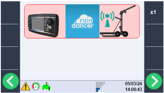
-
On the main page, click the cloud icon with the gear symbol
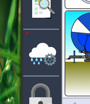
-
Click the "DIGITAL" button to switch to the Raindancer dependency mode

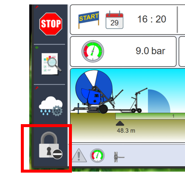


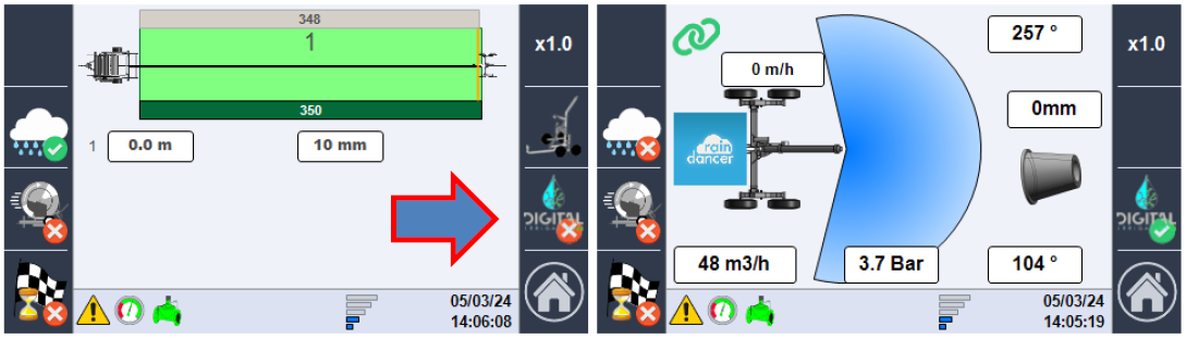
Irrimec Dosidis+ IP
Part 1: Setup on the Dosidis+ Device
What do you need?
-
Device switched on and ready
-
Appropriate SIM card (Raindancer or your own)
-
Access data (APN) – you will receive this from your dealer or service provider
Setup steps:
First, insert the SIM card into the device. Detailed instructions can be found in the manual under section 7.C (page 32).
What to do if the connection fails:
-
Verify the APN, URL, and port data have been correctly entered.
-
Check network reception at your location.
-
Restart the device to establish a fresh connection.
We recommend for Using the remote control a firmware of
- Dosidis+ of Irreg13 3 03 (11.02.2026) or higher
- Dosidis2 of Irreg12 6.02 (11.02.2026) or higher
Part 2: Integration into Raindancer (only by a service partner)
This part will be carried out by your Raindancer service partner.
-
Provide your service partner with the previously noted IMEI number.
-
The service partner will register the IMEI in the Raindancer system under:
-
Menu item: "Edit Irrigator" → "Irrigator Control"
-
Select control type: Irrimec Dosidis+ IP
-
Beinlich 4KR
Create API users in Raindancer
Create a new user in the user overview on the Raindancer Portal
Username: API User
Password: You decide this!!! PLEASE MAKE A NOTE OF IT!!!
Store API user data in the Beinlich Cloud
Logging into the Beinlich Cloud
- Open the Beinlich Cloud using the following link:
https://everrain.beinlich-beregnung.de - Log in using your personal credentials.
These are provided by Beinlich. - In the top menu, navigate to the “Connection” section.
- Enter your login credentials.
- Click on “Test Connection”.
- If a green check mark appears, the connection was successful.
- Finally, click “Save” in the bottom right corner to store your settings.
If the connection test fails, please check the API user in the Raindancer portal again as well as the entries in the Beinlich Cloud. If it still does not work, please contact your Beinlich partner or Raindancer.
Configuration in the Raindancer Portal
- Switch to the Raindancer portal.
- Open the irrigator overview.
- Select the desired irrigator and click “Edit” in the corresponding row.
- Navigate to the “Setup and Control” tab.
- Select “Beinlich API” as the control type.
- Then choose the appropriate control device from the dropdown menu.
This device is named after your irrigation system in the Beinlich Cloud
Where to Find the SWS Number on the Machine. The SWS number can be found in the main menu of the Beinlich controller. Alternatively, you can open the controller and read the SWS number on the inside of the cover. Please note that it may be difficult to access or read due to internal wiring.
Configure the Beinlich Controller before first use
If the machines are not yet displayed online in the Beinlich Cloud during the initial setup, this may be because the controllers first need to be configured.
The configuration can be completed easily in just a few steps. Please follow the step-by-step guide in this 4KR Verbinden mit dem Everrain Portal (2).pdf.
Costs
Billing for the Beinlich Cloud, including the SIM card, is handled directly by Beinlich and charged to the end customer.
As of April 22, 2026, the annual fee is €100.
Integrate third-party weather sensor data into Raindancer
The integration of weather sensor data into Raindancer takes place in the following steps:
- The API access to the third-party provider must be stored in Raindancer so that Raindancer can obtain data from there.
- Raindancer synchronises the weather stations, sensors and measurement data from the last week in the background.
- A measurement point must be created in Raindancer to summarise sensor data in diagrams and link sensor data to fields.
Creating an API access
It is currently possible to integrate sensor data from Weenat and Pessl. For more information, see the relevant articles:
For Weenat, you can use the user data for the Weenat portal. For Pessl, you have to create API keys separately in the Pessl portal: Create Pessl key.
Synchronisation of sensor data
After setting up an API account, Raindancer starts synchronising data in the background. Weather stations, sensors and sensor data from the last week are transferred.
An overview of the synchronised weather stations can be found under Measurements > Weather stations.
Synchronisation currently takes place every 65 minutes. This means that it can take up to 65 minutes for the weather stations to appear in Raindancer. Changes and new sensor data are then transferred every 65 minutes.
Creating measurement points
Measurement points in Raindancer are used to group sensors and assign them to fields.
To create a new measurement point, go to Measurements > Measurement points in Raindancer and select New measurement point.
Here you enter the measurement Spot:
- A designation
- A position for display on the map
- An assigned field
- A list of sensors, which can come from different weather stations
After saving a measurement point, the following diagrams can be found on the measurement Spot details page, depending on the assigned sensors:
- A precipitation diagram
- A soil temperature diagram
- An air temperature diagram
- A soil water potential diagram
- A soil moisture diagram
If soil moisture sensors are available, the following are also displayed:
- A diagram of the current water content
- A diagram of the irrigation recommendation
- A current irrigation recommendation
The irrigation recommendation and the current water content are also displayed on the map.
The following diagrams, which are combined from the sensors of all measuring Spot, are displayed on the overview page for measuring Spots:
- A precipitation diagram
- A soil temperature diagram
- An air temperature diagram
Linking Raindancer with the Pessl API
Raindancer can automatically download and continuously update weather data from a Pessl weather station using Pessl's public API.
To register Pessl API access in Raindancer, go to Settings and then to the API sub-item.
There, click on ‘New API credentials’. In the following menu, you can choose between ‘PESSL FieldClimate API (Legacy)’ and ‘PESSL FieldClimate API v2.0’ under API type.
‘PESSL FieldClimate API (Legacy)’ is the old API access method and should no longer be used.
Select ‘PESSL FieldClimate API v2.0’ and then enter the public and private keys, which can be obtained from the FieldClimate homepage.
Once you have saved the keys by clicking ‘Save’, Raindancer can begin importing the available measurements. This may take > 20 minutes, as Raindancer retrieves the data at fixed intervals.
Generate keys
To enable Raindancer to automatically retrieve data from the Fieldclimate API, you need a private and a public key from Fieldclimate.
To create the keys, first log in to the Fieldclimate homepage (e.g. ng.fieldclimate.com). Then go to the user menu, which can currently be accessed via the person icon in the top right-hand corner, and select API services.
If the keys have already been created, they will now be displayed.
Both keys consist of 48 hexadecimal characters (0-9 and a-f). If the keys have not yet been created, you can create them now by clicking on the ‘Create new’ button.
At the top right of the API key area, there is a question mark button that you can click on to get more information about key creation.
Connect Raindancer to the Weenat-API
To link weather data from Weenat to Raindancer, you need an account with Weenat (https://weenat.com/).
Raindancer Portal instructions:
- Go to Expert mode (top right).
- The Weenat account must then be registered in Raindancer under Settings > API > New API login details.
- Select Weenat API under API type.
- Enter your Weenat login details (username and password).
- Save your changes.
-Note: It may take more than 20 minutes for the first data to be synchronised.
- Then save and close the application.