Troubleshooting in Raindancer
Here you will find simple answers to the most common problems and difficulties when using Raindancer
- Replace motorbox base plate assembly
- Install the Motor Box Correctly
- Troubleshooting the Beacon
- Remove the Motor Box Gasket
- WhatsApp Notifications are not Working.
- Troubleshooting the Sector Control
- FAQ - Frequently asked Questions
Replace motorbox base plate assembly
In these guide, we will take you through the necessary steps to replace the base plate including the motors.
This is only necessary if your motors are faulty and you have been sent a replacement kit.
The removal of the box is identical:
Removing the motor box
Removing the base plate
- Loosen the 4 screws on the base plate. (Torx T-10)
- Carefully remove the base plate.
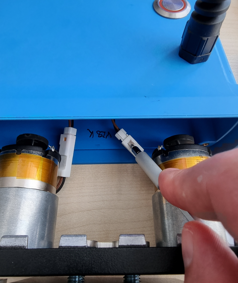
- Disconnect the cable connection of the motors to the plugs inside the box.
To release the connection, carefully press in a clip on the plug connection.
It is best to use a slim flat-head screwdriver to press the clip down.
This step can be fiddly. Take your time.

-
Place the new base plate and align the plate so that the cables inside the box are on the same side as the cables on the motors and plug in the connectors.
-
Now insert the base plate all the way
-
Switch on the motor box to check that both motors are turning. Listen out for any grinding noises from the tops on the motor shafts.
-
-
Now screw the base plate back into place using the appropriate screws.
 For the subsequent installation, follow the instructions for installing the motor box correctly from here
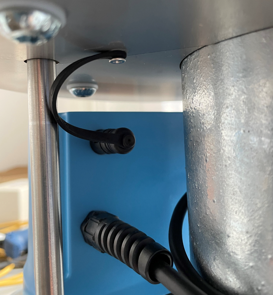
Do NOT Forget Your Cap
After installing the motor box, make sure to put the protective cap on the extension connection
Check whether the sector control is executing the commands you send from the app correctly.
Install the Motor Box Correctly
In this guide, we will explain the steps you need to take to repair your motorbox.
Mounting Details
The position of the connectors on the 2021 sector controls has been changed for the sake of ongoing optimisation.
However, motor boxes of the 2021 generation are still compatible with the sector controls from the previous year.
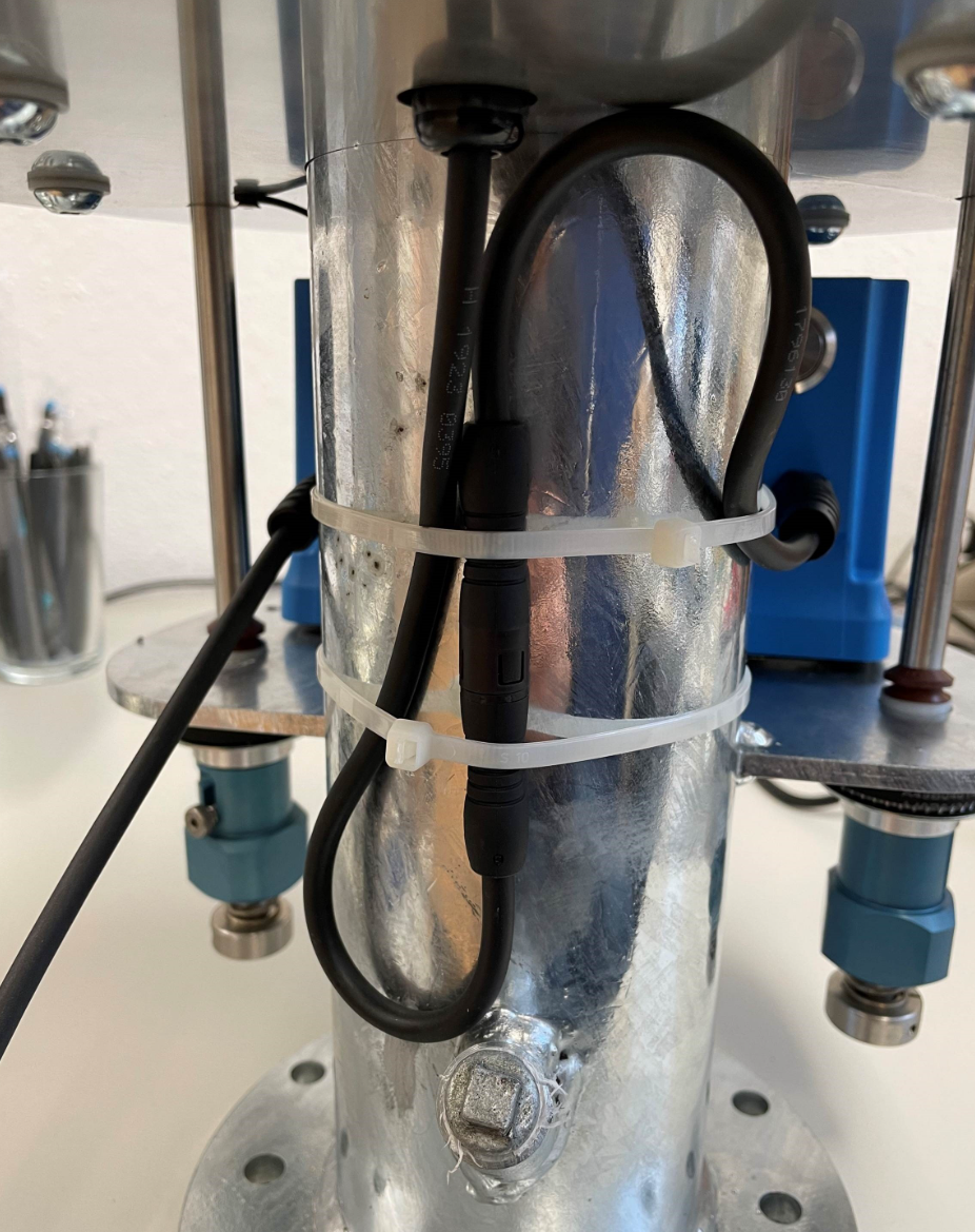
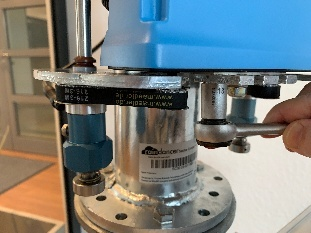
Only the cable connection appears unnecessarily long due to this change and requires fixing as shown in the following picture.
Please ensure that the cable is laid without kinks in a loose "S" Shape and fix it with the cable ties supplied at the point shown in the photo to prevent the plug connection from becoming entangled.
Nullpunkt
If a zero point has been set for this sector control, this may not yet be known to the new motor box. If the sector control is switched on and the Raindancer module is connected and loaded, the software will automatically attempt to assign this value to the new box.
Nevertheless, we ask you to check the correct alignment of the sector control before using it for the first time.
Guide

Insert the new box into the designated cut-outs. The cables must point towards the tube and be routed between the tube and the drive shaft.
-
Make sure to mount the spacer plate on the motor box above the mounting plate of the sector control. This plate ensures the correct distance to the mounting plate.
If you have not placed the spacer plate between the motor box and the frame, the motor box may be warped and the belt drive may not be able to work properly.
 Place the belts over the belt pulleys of the shaft and the motor.
 - Tension the belt with one hand by pushing the motor box forwards and tightening the nuts under tension. The belts should be tight, but not so tight that they can no longer be squeezed in and must not be allowed to skip.
- Fit the belt caps over the belts and belt pulleys.
- Connect the short cable to the stop sensor and (for sector controls from 2020) lay it in a loose S on the riser tube and secure it with the cable ties provided.
- Caution: Do not forget to put the cover cap on the upper extension socket.
- Switch on the motor box at the on/off switch and check that both stops are moving. After a short time, the stops should stop and return to their original position.
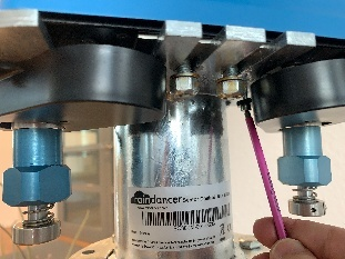
Please do not forget to engage the couplings on the bottom side.
Troubleshooting the Beacon
Compatibility check:
-
- Beacons are immediately ready for use on the Ethernet module (in combination with a router with active DHCP).
- There is a known incompatibility with certain versions of the Ethernet module
(specifically: Rev.4.2, labelled accordingly on the board).
In this case, the automatic detection and configuration of the Ethernet module fails
(see "Troubleshooting" point 2.a.i.)
- There is a known incompatibility with certain versions of the Ethernet module
- Beacons are immediately ready for use on the Ethernet module (in combination with a router with active DHCP).
- Beacons specially preconfigured for operation with the GSM/GPRS modem cannot be used with the Ethernet module1.
- To establish a data connection, corresponding access data is stored in the configuration, which depends on the respective network operator/provider. When changing the SIM card, this must be taken into account and adjusted if necessary.
Notes:
1) This would require the configuration stored in the beacon's internal memory to be adapted again; only possible via a serial direct connection to the beacon via USB.
Troubleshooting
-
Wiring / connections OK?
-
Beacon is connected to external power supply?
No power supply for Ethernet module or GSM/GPRS modem via USB! -
For combination of Ethernet module and router:
-
Ethernet module and router connected via Ethernet cable?
-
Is the correct port on the router being used?
If there are several ports, connect to sockets labelled "LAN" if possible.
("WAN" port can usually be used as an additional "LAN" port on routers set up by us) -
Check the connectivity of the router!
-
Check the signal strength LEDs on the front of the router.
-
Antenna(s) connected?
If there are several "mobile" antenna connections, connect all antennas correctly!
If necessary, use wired antennas and select a more suitable location! -
If possible, establish a connection via Ethernet cable and check the router administration.
-
Try to access http://192.168.1.1. The router's status page should show the connection status
-
It should be possible to call up a website, e.g. www.google.de. If so, it is most likely not due to the router and its configuration.
-
If necessary, log into the admin interface and check the configuration
-
-
SIM card activated?
- Check connection between Beacon and Ethernet module or GSM/GPRS modem.
If necessary, replace the PCB connector / ribbon cable. - Under certain circumstances, strong electromagnetic interference in the environment can cause interference to the wireless signal or incorrect states in the memory / program sequence (beacon and router / modem).
In such situations, ensure sufficient shielding, use external wired antennas if necessary and place them at a sufficient distance.
-
-
-
- Is the Beacon (still) running??
- What is displayed on the screen?
The bottom text line specifies the last status
- "writing FRAM" (since v2.2.0 "Search Ethernet" / "No Ethernet") There is a problem with the Ethernet module.
A brand-new Beacon arrives without a configuration and attempts to create a default configuration for the Ethernet module when it is started for the first time. The beacon attempts to address a part (the FRAM chip) that is only present on the Ethernet module; if this is found and functions correctly, the beacon configures itself for operating with the Ethernet module.
In rare combinations (so far only recorded: Ethernet module of revision 4.2 in combination with older Beacon serial numbers), this component cannot be addressed correctly. The Ethernet module must be replaced, e.g. with one from revision 5.0. Unfortunately, the revision number is only visible on the circuit board of the Ethernet module (remove the housing cover). - "Not Configured" or "Config faulty" There is a problem with the configuration of the Beacon.
With older firmware versions (1.x), the configuration is stored on an external SD card (placed in the Ethernet module or the GSM/GPRS modem). In the past, oxidation on the contacts of the SD card slot could lead to problems when reading. Carefully remove the SD card (push in carefully, the card will pop out a little), degrease the contacts and push it back into the card slot.
Newer firmware versions (from 2.0) store the configuration in the internal EEPROM, separately from the device identification. As long as the device identification can be read, at least one basic configuration (contact to the live system, analogue inputs and outputs in 4-20mA current loop mode) can always be reverted to. The service life of the internal EEPROM is limited in terms of maximum write cycles (100,000e times). - »Not Connected« The beacon cannot establish a connection to the server (see 1.)
Other possible status messages that indicate an unsuccessful connection to the server are: "Conn. Failed", "Timed Out", "Invalid Server", "Truncated", "Invalid Resp.", "Domain Not Found" or "Connect. Error" indicate that a network connection could be established, but problems occurred when contacting the Raindancer servers. In addition to the steps under point 1 (in particular 1.iii.3, you should try to access the Raindancer web portal at https://portal.myraindancer.com/ via a direct connection to the router). - »Send Status« the current status of the inputs and outputs is or has been transmitted to the server.
This is the usual state.
- "writing FRAM" (since v2.2.0 "Search Ethernet" / "No Ethernet") There is a problem with the Ethernet module.
-
Can the backlight / menu be activated by pressing the buttons on the display?
If this fails repeatedly and the status indicator on the display does not change over a longer period of time, this indicates a programme crash.
Note: in certain phases of the programme (e.g. when establishing a connection via GSM/GPRS modem), the beacon does not appear reactively, repeat the test by pressing a button after some time.-
Firmware versions < 0.7.1 should possibly be updated (device replacement).
There was a problem with the 1286 variants when renewing DHCP leases, which could cause the Beacon to crash. -
Firmware versions < 1.2.2 should be reconfigured to static IP.
There was a problem with the D21G variants with considerable memory fragmentation when requesting DHCP leases. -
Firmware versions < 1.1.1. may have problems with serial communication via RS-485 interface.
-
Firmware versions ≥ 0.7 with programme crashes are not yet known; if necessary, check EMC (electromagnetic compatibility) / environment for interference.
-
Under certain circumstances, strong electromagnetic interference in the environment may cause faulty states in the memory / programme sequence.
In such cases, sufficient shielding should be ensured.
-
- What is displayed on the screen?
- Overview of Beacon variants and firmware versions:
- D21G - current hardware variant, firmware versions ≥ 1.1.0
- Firmware version ≥ 2.0.1 sends additional debug information after reconnection (uptime, free memory, frequency of the main loop).
- Firmware version ≥ 2.0.0 supports a remote restart and is handled accordingly in the configuration interface.
- Firmware versions < 1.2.2 should be configured to static IP, as there was a problem with significant memory fragmentation when requesting DHCP leases.
- Firmware version ≥ 2.0.1 sends additional debug information after reconnection (uptime, free memory, frequency of the main loop).
- 1286 - EOL, firmware versions ≤ 1.2.2
- Firmware version 0.7.2 is identical to version 1.0.0.
- Firmware version ≥ 0.7.2 can be reconfigured remotely to static IP.
- Firmware versions < 0.7.1 should possibly be updated (device replacement)?
There was a problem when renewing DHCP leases, which could cause the Beacon to crash.
- Firmware version 0.7.2 is identical to version 1.0.0.
- D21G - current hardware variant, firmware versions ≥ 1.1.0
The Beacon in Pivot Irrigation Systems
"Message without payload" - The beacon does not send any data via the serial connection
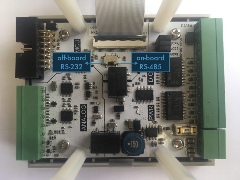
It could be that the internal physical switch is not set correctly. The switch is located inside the Beacon.
The switch should be set towards the 14-pin connector to enable serial communication via RS-232.
Remove the Motor Box Gasket
This section explains how to remove the gasket between the base plate and the blue box cap.
It is possible that the electronics of the motor box do not correctly detect the revolutions of the motors, which either leads to a blocked stop error message or to the sector control occasionally controlling slightly incorrect angles.
Toolkit
- Allan Key 3 mm
- Wrench 13 mm
-
TORX 10
Dismounting the Motor Box
The motor box is dismounted in exactly the reverse order to installation. [Install the Motor Box Correctly]
-
Switch off the motor box.
-
Use the Allen key to loosen the two screws on the caps above the belts.
-
Use a 13 mm open-end wrench or a ratchet with a suitable socket to remove the two central nuts
underneath the motor box. -
Remove the belts from the belt pulleys.
-
Disconnect the cable that runs from the motor box to the sensor above it.
-
Remove the blind cap on the back of the motor box.
-
You can now pull the motor box forwards out of the guides.
Should I Remove the Gasket?
The motor box can be opened by removing the 4 TORX-10 screws.
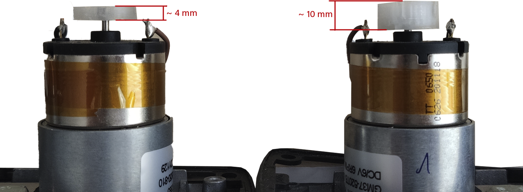
To decide whether removing the seal is the solution for you, look at the magnetic discs on the motors.
If your motors are equipped with smaller magnetic discs, it may help to remove the rubber gasket.
Removing the gasket allows the base plate to come around 2 mm closer to the sensors in the cover of the motor box, so that the revolutions of the motor can be counted correctly again.
You can simply pull the gasket down over the base plate without having to disconnect the motor cables.
If your base plate is already equipped with the bigger magnetic discs, this fix will not help and you will therefore need a base plate with new motors. Please contact our support team and we will organise the shipment of a replacement part as quickly as possible.
You can find more information on this topic here Replace motorbox base plate assembly
Installing the Motor Box
To install the motor box, please follow these instructions.
-
Insert the motor box with the spacer plate directly pressed on the base plate of the motor box in the mounting.
-
Slip on the belt.
-
Tension the belt by pulling the motor box forwards.
-
Make sure that you tighten the belts, but neither too tightly nor so that the belts can skip.
Ideally, you can still squeeze the belt together a little -
Tighten the nuts under the motor box one after the other under tension.
-
Now plug the cable from the motor box into the upper sensor.
-
Set the stops to a +90/-90 position (semi-circle) and switch on the motor box.
-
Switch on the motor box.
-
After successful adjustment, you can refit the belt cover
-
Do not forget the blind cap on the back.
WhatsApp Notifications are not Working.
If you do not receive any notifications via WhatsApp, this may be because WhatsApp has not authorised your telephone number to communicate with business accounts. Unfortunately, we can't automatically check the WhatsApp messages reaching you.
In case you are not sure if your phone number is activated, please follow one of the two approaches:
Option 1: Confirmation of the policies via WhatsApp
Click here
OR
-
Create a new contact called "Raindancer Support" on your mobile phone. The service telephone number is:
+49 30 89 00 61 70. -
Open WhatsApp and search for the contact you created, "Raindancer Support".
-
Send a message with the text: "WhatsApp confirmation" to this contact.
-
A new WhatsApp window will appear asking whether you like to approve communication with business accounts. Please confirm this message.
-
You are welcome to test the correctness with the test send function in the user settings
Option 2: Switch to Text Message or e-mail
-
Select the desired communication channel (SMS or e-mail).
-
If you choose SMS, please remember to confirm the costs and tick the appropriate box.
-
Send yourself a test message to make sure that there are no transposed numbers in the telephone number or spelling mistakes in the e-mail address.
Troubleshooting the Sector Control
The following assistance applies to sector firmware version 36 and newer. For older versions, errors may have different causes.
Ensure that your Raindancer sector control is switched on and connected to a transmitting Raindancer module.
All error messages from the sector control should be taken seriously!
If the position of the stops cannot be determined accurately, the display on the smartphone may be incorrect and calculations can be wrong.
Error List
The sector control distinguishes between four different errors. We will go through each one and show you potential countermeasures to prevent further damage.
1. Turned Off or Connection Lost
This error indicates that the Raindancer panel and the motor box of the sector control cannot establish a connection. In most cases, this is because the sector control is switched off or a cable connection is defective or loose.
On older software versions, it may also be due to a wrong configuration. After checking cables and the switch, we recommend performing a firmware update (version P32 or higher) to rule out this cause.
What You Must Do:
-
Check the cable connection between the Raindancer GPS module and the motor box for:
-
Proper seating
-
Bent or damaged pins
-
Water or corrosion damage
-
-
Make sure the sector control is switched on.
-
Ensure that your Raindancer module is already connected to the Raindancer cloud and is sufficiently charged.
If you still cannot establish contact with the sector control, please contact customer support to discuss the next step
2. Stop Blocked
This error message means that one or both stops cannot move as intended. In this case, first check the moveablility of the sector control.
Steps for Checking:
-
Decouple the stops Release the blue couplings at the lower end of the sector control to decouple the stops.
-
Manual Inspection of the Stops
-
Turn each stop by hand a full 360°—this should be possible without significant force.
-
Check for any grippy spots.
-
If a stop is unusually grippy, the sector should be cleaned or serviced (an instructional video is available).
-
-
Check Behavior on Start-Up
-
Switch on the sector control using the rear switch.
-
Expected Behavior:
-
Both motors move.
-
If the stops are coupled, the arms move about 20 degrees and then return to the starting position.
-
-
-
Possible Causes of Motor Non-Movement:
-
Defective Motor: If only one motor remains still, that motor is likely defective.
-
Power Supply: If both motors do not respond, the sector control may lack sufficient power.
-
Check whether the connected Raindancer GPS module is functioning and has had enough sunlight to charge sufficiently to power the sector control .
-
-
If the above checks do not resolve the issue, customer support may be able to help via configuration adjustments.
-
-
Sensor Malfunction If both motors work normally but the message “Stop Blocked” still appears, there is likely an issue with the sensors on the motors.
When to Contact Support: If the error persists, please reach out to customer support.
Quick Self-Help for Older Sector Control
Follow our instructions for removing the motor box gasket.
In Short:
-
Check free movement in the decoupled state.
-
If the sector is stiff, wait and perform maintenance.
-
If only one motor turns or the error persists during movement:
-
Possibly remove the seal.
-
Inform support.
-
-
If both motors do not turn:
-
Ensure power supply.
-
Check cables.
-
Inspect the Raindancer GPS module.
-
Allow enough time for charging.
-
-
If both motors do turn:
-
Sensor issue likely.
-
-
If the problem continues, please contact us.
3. Stop Angle Unknown
This error message means that the sector control cannot determine its exact position. Although a blocked motor could also cause this (in which case both error messages would appear), the usual cause is a fault in the upper sensor.
Key Points:
-
Position detection is not based solely on the motor but also on a sensor located between the upper rings.
-
For this sensor to work correctly, the cable connection from the motor box to the upper sensor must be flawless.
What You Must Do:
-
Check Cable Connection Inspect the connector between the motor box and the upper sensor:
-
Are all pins present and undamaged?
-
Does the connector sit firmly and without wiggle?
-
Is the connector housing intact (no cracks or breaks)?
-
-
Exclude Prior Errors Ensure that the error message “Stop Blocked” has already been resolved (see the corresponding section above).
When to Contact Support: If the error persists after checking the cable connection and ruling out a blocked stop, please contact customer support to discuss the next steps.
4. Stop Decoupled
This error message indicates two possible problems:
-
Physical Decoupling of the Shaft The shafts are connected to the motors via the blue couplings at the lower end. In the coupled state, it should be impossible to move the stops by hand.
-
Same Cause as “Stop Angle Unknown” If no physical decoupling is present, the error can have the same cause as “Stop Angle Unknown” (e.g., sensor or cable issues).
What You Must Do:
-
Check If the Stops Are Truly Decoupled
-
Release the blue couplings to separate the shaft from the motor movement.
-
Turn the stops by hand:
-
Do they now move freely?
-
If yes, physical decoupling is normal.
-
-
In the coupled state, the stops should not turn by hand. If they do, check the following points.
-
-
Inspect These Points if the Stops Are Unexpectedly Loose
-
Locking Screw: Is the screw on the coupling present and tightened?
-
Motor Pulley (Riemenrad):
-
Remove the belt cover and try to turn the pulley by hand.
-
The pulley must not turn by hand.
-
-
Upper Stop Pinion (Ritzel):
-
You should not be able to see or reach the pinion from the outside. If any of these components are missing or loose, the stop may be decoupled when it should not be.
-
-
-
Exclude Cause “Stop Angle Unknown” If all mechanical components are intact and the stops still cannot be located, the cause may be the same as for the error “Stop Angle Unknown.” Proceed as follows:
-
Check the cable connection from the motor box to the upper sensor (see the section "Stop Angle Unknown").
-
Ensure connectors are fully seated and pins are undamaged.
-
When to Contact Support: If the problem continues after checking the mechanical couplings and sensor wiring, please contact customer support to determine the next steps.
FAQ - Frequently asked Questions
"No registered devices for push notifications were found for this user."
Introduction
Our app sends important information via push notifications.
To ensure these messages are displayed, notification permissions must be enabled in your device’s operating system (Android or iOS).
If you tapped “Don’t Allow” when the app first asked for permission, you can enable notifications later in your device settings.
This guide shows you step by step how to do that.
Enabling Push Notifications on Android
Step-by-Step Instructions
- Open the Settings app on your Android device.
- Scroll down and tap Apps or Apps & Notifications.
- Select our app from the list.
- Tap Notifications.
- Turn on the switch for Allow notifications.
- Make sure that individual notification categories (if displayed), such as Messages, Alerts, or Updates, are also enabled.
Note
Depending on your device manufacturer (Samsung, Xiaomi, Google Pixel, etc.), menu labels may differ slightly.
The procedure, however, remains mostly the same.
Enabling Push Notifications on iOS (iPhone/iPad)
Step-by-Step Instructions
- Open the Settings app on your iPhone or iPad.
- Search and Tap Notifications.
- Scroll down and select our app from the list.
- Enable the switch Allow Notifications.
- Choose how you want the notifications to appear:
- Lock Screen
- Notification Center
- Banners
- Optional: Enable Sounds or Badges if you want audio alerts or visual indicators.
How Do I Know It’s Working?
- The message “No registered devices for push notifications were found for this user.” will no longer appear in the portal.
- After sending a test message from the user settings, you will see a new notification in the app’s notification area.
Frequently Asked Questions
Why do I have to enable this manually?
If you deny notification permission the first time the app asks, the app is not allowed to request it again.
This is a security feature of the operating system.
Is it safe?
Yes. Push notifications simply inform you about new content.
We do not access any personal data when you enable notifications.