**EXAMPLE** A pressure adjustment is made via a **0-10 V** signal. The saved value range of **0 to 16 bar** results in an output signal of 5 V when selecting a target pressure of 8 bar.
#### Outputs With the two analogue outputs, you are free to choose what you want to use them for. By default, we use them to control pressure. However, if your application deviates from the standard, you can use the **user-defined option** to specify a name for the input and a corresponding unit of measurement. The measuring unit is used together with the value range. In addition to the value range and the mode, you also have the option to activate **manual** changing of the value via the app or the web portal. You can also customise this option by setting a value range and a corresponding increment that is available for manual adjustment. [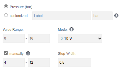](https://help.raindancer.com/uploads/images/gallery/2024-04/9wiimage.png) **Example** In this scenario, it is possible to select a manual value between 4 and 12 bar. The options for setting this value would each be in 0.5 bar intervals. In this example, you therefore have the option of setting the pump to 6.5 bar with a target pressure, but not to 7.2 bar or 13 bar As you can see, you can customise your outputs here and adapt them to your individual application. #### Inputs With the four analogue inputs, you are free to choose what you want to use them for. In the standard version, we assume pressure, power, flow and rotation speed. However, if your application deviates from the standard, you can use the customised option to specify a name for the input and a corresponding unit of measurement. The unit of measurement is used together with the range of values. [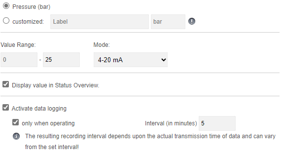](https://help.raindancer.com/uploads/images/gallery/2024-04/n9Ximage.png) **Options and visibility** This information is displayed on the details tab of your pump, accessible through both the app and the web portal. You can view this value whenever you wish. Activating the logging options enables you to monitor the pressure values of your pump in detail and see them in the reports. ##### Meter Reading The Beacon allows you to connect a digital water meter and automatically log water consumption. Alternatively, you can also use the same input to connect a rain gauge. You must select the appropriate option and enter the corresponding meter tick. The meter tick determines how many ticks are required for one litre of flow.Please remember that if you **change the mode of the analogue inputs and outputs**, you must **send the configuration to the Beacon** for the changes to take effect.
#### Error Codes & Digital Inputs You have the option of freely setting the error codes that your Beacon can display. There are 3 digital inputs available for this purpose. Depending on which inputs supply which signal, a combination of 7 different error or status messages are generated, which you can see on the app and be notified of. The standard configuration is as shown below:| CODE | TYPE | Default Message |
| **0-0-1** | Error Code | Frequency Inverter / Pump |
| **0-1-0** | Error Code | Motor temperature |
| **0-1-1** | Error Code | Restart after interruption of the power supply |
| **1-0-0** | Error Code | Generic Pressure Error |
| **1-0-1** | Error Code | Exceeding Pressure Limit |
| **1-1-0** | Error Code | Pressure Limit Undercut |
| **1-1-1** | Error Code | Remote control OFF |
Please keep in mind that if you **change the pulse length** at the digital outputs, you must **send the configuration to the Beacon** in order for the changes to take effect.
# Technical Data - [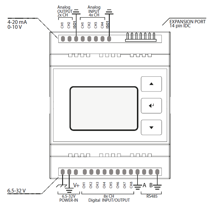](https://help.raindancer.com/uploads/images/gallery/2024-03/9U0image.png)ATSAMD21G18 Microcontroller - 128x64 px LCD Screen with Backlight - Membrane 3 Button Panel - Ethernet Module (mandatory) M2M 3G/LTE Router optionally available - Standard Input Voltage: 12V / 24V DC permissible range: 8–28V DC 12V, 24V PSU optionally available - DIN-Rail mountable - 4 Analog Input Channels - 2 Analog Output Channels - Levels: 4–20mA / 0–10V - Fully isolated from MCU and Digital Side (1kV isolation) - 8 Digital I/O Channels - Digital Input Voltage Range: 0–28V input channels internally driven LOW - Digital Output Vortage Range: 8–28V (tied to VIN) - Digital I/O Levels: LOW ≤ 3V, HIGH ≥ 11V I/O Logic is active high - Max. Output Current per Pin: 2.6A (short circuit, over-current, over-temp. protected) - Max. Total Output Current: 6.5A (omni block fused) - Fully isolated from MCU and Analog Side (1kV isolation) - Isolated Half Duplex RS-485 Transceiver #### Important Notes To properly operate the Raindancer Beacon, it has to be connected to an adequate power supply via the POWER-IN field (12/24V DC is recommended). The USB port on the front casing is not suitable. When a single power supply is used to power both, Raindancer Beacon and peripherals, the GND lines should be tied together.Power down all systems (Raindancer Beacon, sensors/actuators) before connecting to the Raindancer Beacon via USB, internal components may irreparably take damage otherwise!
#### Analog Field Section - Analog Pins can be individually configured, according to the requirements of the devices to be connected: 0-10V or 4-20mA. By default, all Analog Pins are preconfigured to 4-20mA. An alternate configurations can be set using the web-portal. Pin Assignment and Value Ranges when Used as Pump Control Unit: - The value ranges can be individually adjusted using the web-portal.| A OUT | Assignment | Default Range |
| CH 1 | Target / Min. Pressure | 0 – 16 bar |
| CH 2 | Manually Set Pressure | 0 – 16 bar |
| A IN | Assignment | Default Range |
| CH 1 | Current Pressure | 0 – 16 bar |
| CH 2 | Current Power | 0 – 100 kW |
| CH 3 | Current Flow | 0 – 100 m³/h |
| CH 4 | Current Speed | 0 – 3.600 rpm |
| D CH | Assignment | Signal | Interpret. |
| **1 (OUT)** | Control ON | Pulse, 125ms | ON |
| **2 (OUT)** | Control OFF | Pulse, 125ms | OFF |
| **3 (IN)** | Confirmation | Permanent | ON/ OFF |
| **4 (IN)** | Error Code 1 | Permanent | ON/ OFF |
| **5 (IN)** | Error Code 2 | Permanent | ON/ OFF |
| **6 (IN)** | Error Code 3 | Permanent | ON/ OFF |
| **7 (OUT)** | Reset Error | Pulse, 2s | |
| **8 (IN)** | Counter | Pulse |
| Code 1 (CH 4) | Code 2 (CH 5) | Code 3 (CH 6) | Interpretation |
| 0 | 0 | 0 | no malfunction |
| **1** | 0 | 0 | Malfunction - Pressure, generic. |
| 0 | **1** | 0 | Malfunction - Motor Temperature |
| 0 | 0 | **1** | Malfunction - Frequency Inverter / Pump |
| **1** | **1** | 0 | Malfunction - Low Pressure |
| **1** | 0 | **1** | Malfunction - Excess Pressure |
| 0 | **1** | **1** | Restart after Interruption of Power Supply |
| **1** | **1** | **1** | Remote Control Disabled |
| **Front Panel** | **Rear Panel** |
| [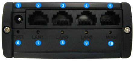](https://help.raindancer.com/uploads/images/gallery/2024-03/kgnimage.png) | [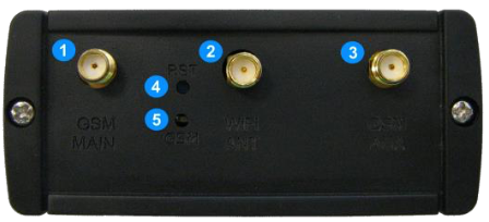](https://help.raindancer.com/uploads/images/gallery/2024-03/RVzimage.png) |
| **1** Hollow Pin / Terminal Block Port Power Supply **2, 3, 4** LAN Ethernet Ports **5** WAN Ethernet Port **6** Status LED Power Supply **7, 8, 9** Status LED LAN Ports **10** Status LED WAN Port | **1** GSM Main Antenna Connector **2** Wi-Fi Antenna Connector **3** GSM Aux. Antenna Connector **4** Reset Button **5** Status LED GSM |
| [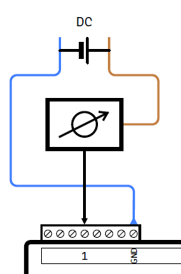](https://help.raindancer.com/uploads/images/gallery/2024-03/gKhimage.png) | Connecting an analog sensor (AIN field) or analog actuator (AOUT field) in series **Typical application:** Sensors and actuators as a dual wire current loop (4–20mA) variant. | ||||||||
| [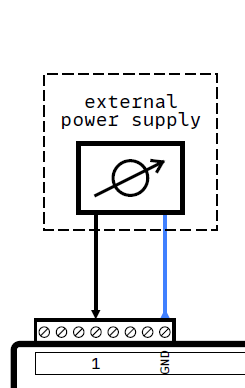](https://help.raindancer.com/uploads/images/gallery/2024-03/b1Eimage.png) | Connecting an analog sensor (AIN field) or analog actuator (AOUT field), using an external power supply unit. **Typical application:** Sensors and actuators as a voltage (0–5V, 0–10V) variant. The analog fields GND/ISO terminal may have to be connected to the external PSU’s ground terminal. | ||||||||
| [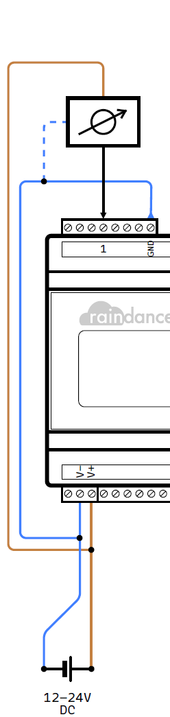](https://help.raindancer.com/uploads/images/gallery/2024-03/afIimage.png) | Connecting an analog sensor (AIN field) or analog actuator (AOUT field), supplied by the same PSU.
**Example:**
ifm pressure transmitter PX9983
on unified current and voltage supply
**Hinweis:** When using separate power supplies, for the Beacon and all connected periphery, a common ground reference should be created by connecting the various ground terminals. **Hinweis:** The illustrations depict common wirings. Always establish a connection according to the instructions from the periphery’s manufacturer. | ||||||||
| [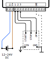](https://help.raindancer.com/uploads/images/gallery/2024-03/xjCimage.png) | Typical connection of a control unit using a pulsed signal (active high, pulse width configurable) for Start (CH1) and Stop (CH2). Feedback of the operational state via permanent signal (active high) via input CH3. Create a common ground reference when using a separate power supply by connecting the GND terminal of the digital field. | ||||||||
| [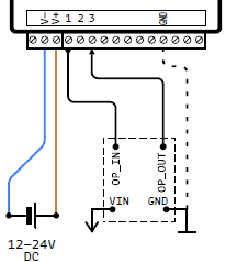](https://help.raindancer.com/uploads/images/gallery/2024-03/UBnimage.png) | Typical connection of a control unit using a permanent signal (optionally configurable) on output CH1 (active high). Feedback of the operational state via permanent signal (active high) via input CH3. Create a common ground reference when using a separate power supply by connecting the GND terminal of the digital field. | ||||||||
| [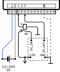](https://help.raindancer.com/uploads/images/gallery/2024-03/zyFimage.png) | Example adaptation to a control unit using a permanent signal (active low) via a NC switch at CH1. Operating directly from CH2’s permanent signal (inverted to that from CH1) is not recommended! Create a common ground reference when using a separate power supply by connecting the GND terminal of the digital field. | ||||||||
| [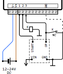](https://help.raindancer.com/uploads/images/gallery/2024-03/cZ5image.png) | Example adaptation for driving an NC switch to pull an active output low in order to stop the connected control. The active output may be used as a feedback of the operational state. Create a common ground reference when using a separate power supply by connecting the GND terminal of the digital field. | ||||||||
| [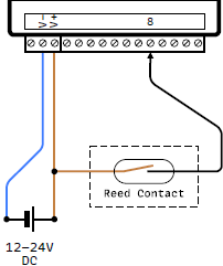](https://help.raindancer.com/uploads/images/gallery/2024-03/M5Kimage.png) | Typical connection of a counter at input CH8. The depicted example uses a simple Reed contact. Alternatively, any kind of impulse generator can be connected to CH8 (input active high). The impulse frequency has to be selected according to the desired application. (Frequency, both flanks ≤ 50/s) |
| ``` Min. measured value: 1,2 Volt ``` | ``` Min. sensor value: 0,2 bar ``` |
| ``` Max. measured value: 9,6 Volt ``` | ``` Max. sensor value: 15,9 bar ``` |
The number of devices configured as »Mirror« are practically unlimited.
[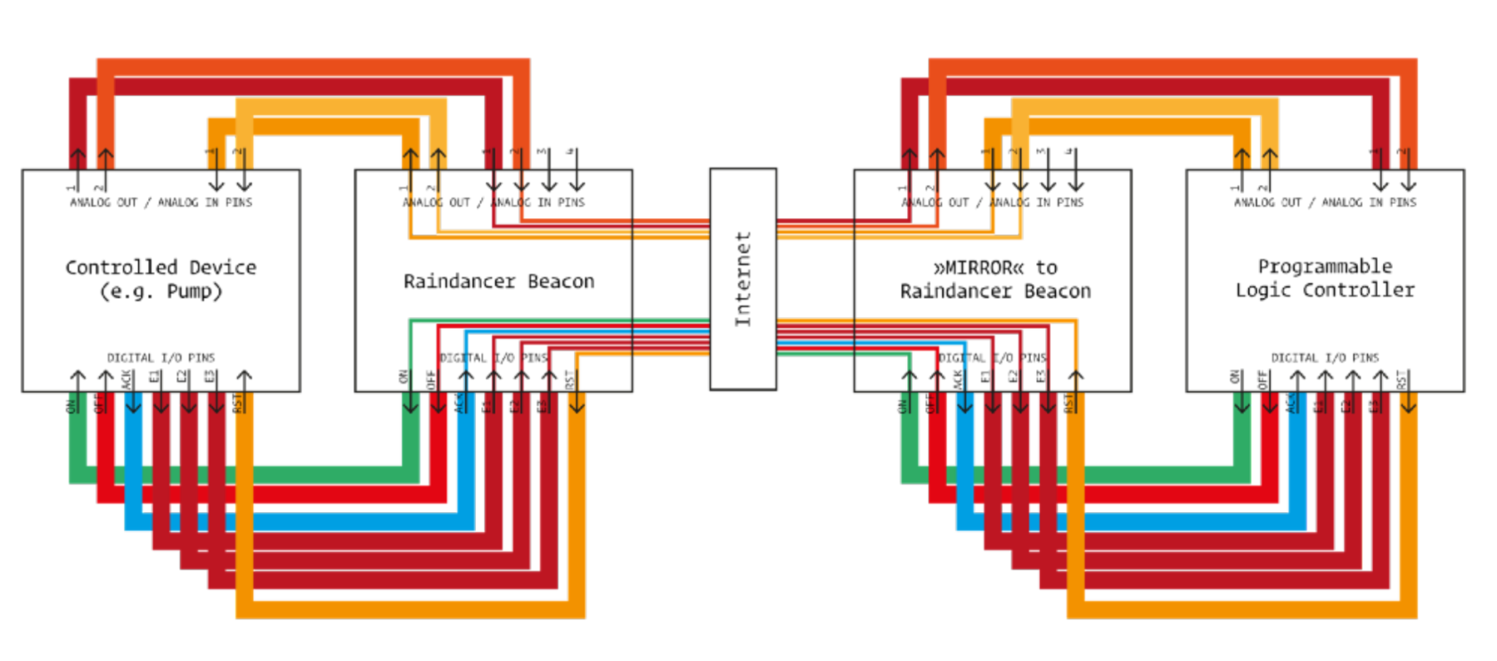](https://help.raindancer.com/uploads/images/gallery/2024-03/PMdimage.png) In order for a Beacon to be able to function as a »Mirror Image«, it has to undergo proper preparation, using a special configuration.