The Raindancer Beacon
The Raindancer Beacon changes the monitoring and control of pump stations, enabling real-time remote management through a web portal or smartphone app, even for those stations where this was not feasible or only possible via SMS before.
- The Pump in Raindancer
- Technical Data
- Initial start-up of the M2M router
- Typical Wiring Variants
- Calibration of Analogue Inputs and Outputs
- Operation Mode »Mirror Image«
The Pump in Raindancer
This section guides you through the most important settings and configurations of the Beacon.
Settings
The settings for the Beacon are quite extensive and complex. In most cases, the relevant settings for the initial setup of the Beacon revolve around the analogue inputs and outputs as well as the error codes and the corresponding messages.
Analogue Connections
Value Ranges
The analogue inputs and outputs each have an operating mode and a value range. These two values indicate how the signal is output or expected and in which ranges the measured values fall. The scaling is linear.
EXAMPLE
A pressure adjustment is made via a 0-10 V signal.
The saved value range of 0 to 16 bar results in an output signal of 5 V when selecting a target pressure of
8 bar.
Outputs
With the two analogue outputs, you are free to choose what you want to use them for. By default, we use them to control pressure. However, if your application deviates from the standard, you can use the user-defined option to specify a name for the input and a corresponding unit of measurement. The measuring unit is used together with the value range.
In addition to the value range and the mode, you also have the option to activate manual changing of the value via the app or the web portal.
You can also customise this option by setting a value range and a corresponding increment that is available for manual adjustment.
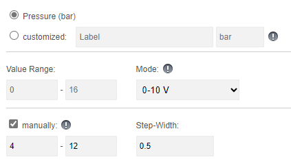
Example
In this scenario, it is possible to select a manual value between 4 and 12 bar.
The options for setting this value would each be in 0.5 bar intervals. In this example, you therefore have the option of setting the pump to 6.5 bar with a target pressure, but not to 7.2 bar or 13 bar
As you can see, you can customise your outputs here and adapt them to your individual application.
Inputs
With the four analogue inputs, you are free to choose what you want to use them for. In the standard version, we assume pressure, power, flow and rotation speed. However, if your application deviates from the standard, you can use the customised option to specify a name for the input and a corresponding unit of measurement. The unit of measurement is used together with the range of values.
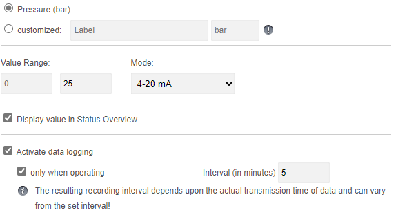
Options and visibility
This information is displayed on the details tab of your pump, accessible through both the app and the web portal. You can view this value whenever you wish.
Activating the logging options enables you to monitor the pressure values of your pump in detail and see them in the reports.
Meter Reading
The Beacon allows you to connect a digital water meter and automatically log water consumption. Alternatively, you can also use the same input to connect a rain gauge. You must select the appropriate option and enter the corresponding meter tick. The meter tick determines how many ticks are required for one litre of flow.
Please remember that if you change the mode of the analogue inputs and outputs, you must send the configuration to the Beacon for the changes to take effect.
Error Codes & Digital Inputs
You have the option of freely setting the error codes that your Beacon can display. There are 3 digital inputs available for this purpose. Depending on which inputs supply which signal, a combination of 7 different error or status messages are generated, which you can see on the app and be notified of.
The standard configuration is as shown below:
| CODE | TYPE |
Default Message |
| 0-0-1 | Error Code | Frequency Inverter / Pump |
| 0-1-0 | Error Code | Motor temperature |
| 0-1-1 | Error Code | Restart after interruption of the power supply |
| 1-0-0 | Error Code | Generic Pressure Error |
| 1-0-1 | Error Code | Exceeding Pressure Limit |
| 1-1-0 | Error Code | Pressure Limit Undercut |
| 1-1-1 | Error Code | Remote control OFF |
Digital inputs
With the digital outputs, you have the option of adjusting the pulse length according to your peripherals. By default, the beacon supplies a 125ms pulse to the corresponding outputs (1, 2, & 7) for starting and stopping as well as for the reset signal
Please keep in mind that if you change the pulse length at the digital outputs, you must send the configuration to the Beacon in order for the changes to take effect.
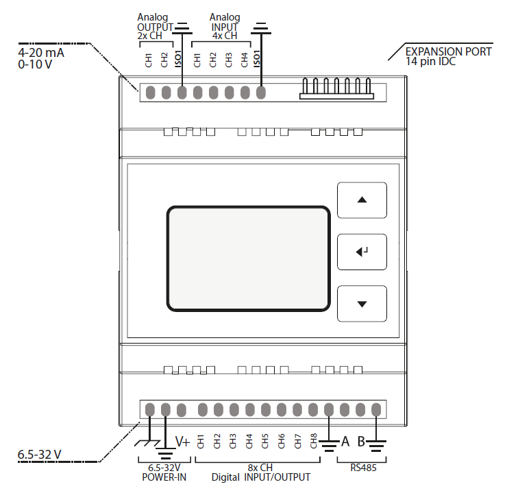
Technical Data
 ATSAMD21G18 Microcontroller
- 128x64 px LCD Screen with Backlight
- Membrane 3 Button Panel
- Ethernet Module (mandatory)
M2M 3G/LTE Router optionally available - Standard Input Voltage: 12V / 24V DC
permissible range: 8–28V DC
12V, 24V PSU optionally available - DIN-Rail mountable
- 4 Analog Input Channels
- 2 Analog Output Channels
- Levels: 4–20mA / 0–10V
- Fully isolated from MCU and Digital Side (1kV isolation)
- 8 Digital I/O Channels
- Digital Input Voltage Range: 0–28V
input channels internally driven LOW - Digital Output Vortage Range: 8–28V (tied to VIN)
- Digital I/O Levels: LOW ≤ 3V, HIGH ≥ 11V
I/O Logic is active high - Max. Output Current per Pin: 2.6A
(short circuit, over-current, over-temp. protected) - Max. Total Output Current: 6.5A (omni block fused)
- Fully isolated from MCU and Analog Side (1kV isolation)
- Isolated Half Duplex RS-485 Transceiver
Important Notes
To properly operate the Raindancer Beacon, it has to be connected to an adequate power supply via the POWER-IN field (12/24V DC is recommended). The USB port on the front casing is not suitable.
When a single power supply is used to power both, Raindancer Beacon and peripherals, the GND lines should be tied together.
Power down all systems (Raindancer Beacon, sensors/actuators) before connecting to the Raindancer Beacon via USB, internal components may irreparably take damage otherwise!
Analog Field Section
- Analog Pins can be individually configured, according to the requirements of the devices to be connected: 0-10V or 4-20mA. By default, all Analog Pins are preconfigured to 4-20mA. An alternate configurations can be set using the web-portal.
Pin Assignment and Value Ranges when Used as Pump Control Unit:
- The value ranges can be individually adjusted using the web-portal.
| A OUT | Assignment | Default Range |
| CH 1 | Target / Min. Pressure | 0 – 16 bar |
| CH 2 | Manually Set Pressure | 0 – 16 bar |
| A IN | Assignment | Default Range |
| CH 1 | Current Pressure | 0 – 16 bar |
| CH 2 | Current Power | 0 – 100 kW |
| CH 3 | Current Flow | 0 – 100 m³/h |
| CH 4 | Current Speed | 0 – 3.600 rpm |
Digital Field Section
- Output can be configured as a permanent or pulsed signal (125ms – 256s).
Signal configuration can be adjusted using the web-portal. - Pulse counter (using level raise/fall, max. ca. 60Hz), e.g. for water meters on Digital Channel 8.
- Please note that floating/pulsing input voltages may be transmitted as highly fluctuating input signals, triggering associated actions (e.g. error notification).
Default Pin Assignment and Value Ranges When Used as Pump Control Unit:
| D CH | Assignment | Signal | Interpret. |
| 1 (OUT) | Control ON | Pulse, 125ms | ON |
| 2 (OUT) | Control OFF | Pulse, 125ms | OFF |
| 3 (IN) | Confirmation | Permanent | ON/ OFF |
| 4 (IN) | Error Code 1 | Permanent | ON/ OFF |
| 5 (IN) | Error Code 2 | Permanent | ON/ OFF |
| 6 (IN) | Error Code 3 | Permanent | ON/ OFF |
| 7 (OUT) | Reset Error | Pulse, 2s | |
| 8 (IN) | Counter | Pulse |
Error Codes
- By combining the three main Error Codes using Digital Channels 4 – 6, four additional states, up to a total of 7, can be transmitted.
- • The textual interpretations of the Error Codes can be customized individually using the web-portal.
Default Error Codes Used by Pump Control/Monitoring:
| Code 1 (CH 4) |
Code 2 (CH 5) |
Code 3 (CH 6) |
Interpretation |
| 0 | 0 | 0 | no malfunction |
| 1 | 0 | 0 | Malfunction - Pressure, generic. |
| 0 | 1 | 0 | Malfunction - Motor Temperature |
| 0 | 0 | 1 | Malfunction - Frequency Inverter / Pump |
| 1 | 1 | 0 | Malfunction - Low Pressure |
| 1 | 0 | 1 | Malfunction - Excess Pressure |
| 0 | 1 | 1 | Restart after Interruption of Power Supply |
| 1 | 1 | 1 | Remote Control Disabled |
Initial start-up of the M2M router
Optionally, the Raindancer Beacon comes with a preconfigured, ready-to-use M2M Router
(M2M – »Machine to Machine Communication«), prepared to be mounted to DIN Rails.
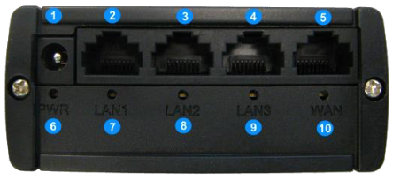
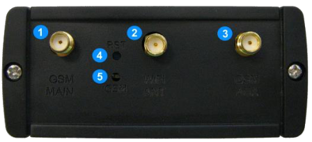
Overview
| Front Panel | Rear Panel |
|
|
|
| 1 Hollow Pin / Terminal Block Port Power Supply 2, 3, 4 LAN Ethernet Ports 5 WAN Ethernet Port 6 Status LED Power Supply 7, 8, 9 Status LED LAN Ports 10 Status LED WAN Port |
1 GSM Main Antenna Connector 2 Wi-Fi Antenna Connector 3 GSM Aux. Antenna Connector 4 Reset Button 5 Status LED GSM |
Setup
- Attach GSM Antenna to Connector [1] on the router’s rear panel.
Note: when lacking imprints, usually the GSM Antenna is the »thicker« one. - Attach Wi-Fi Antenna to Connector [2] on the router’s rear panel.
Note: by default, the preconfigured routers come with Wi-Fi deactivated, when not ordered with an alternative configuration, attaching the Wi-Fi Antenna is not required.
- Connect the Raindancer Beacon(s) via Ethernet cable to one of the ports [2], [3] or [4] on the router’s front panel.
Note: Do not connect the Beacon(s) to the WAN Ethernet Port [5]! - Connect the power Adapter to the rocket on the
router’s front panel [1].
Pay attention to polarity, when connecting to an alternative power source
(9W/9VDC min, 12V rec., 18V/30V max, depending on router model type)!
Typical Wiring Variants
|
|
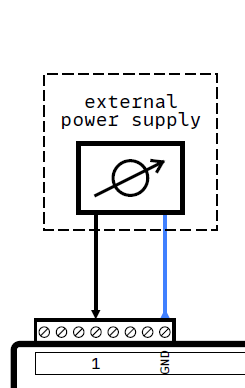
Connecting an analog sensor (AIN field) or analog actuator (AOUT field) in series
Typical application: |
||||||||
|
|
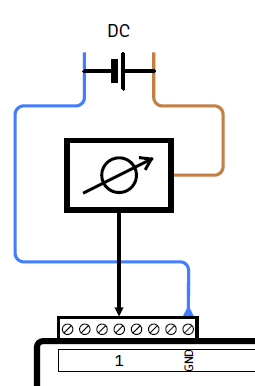
Connecting an analog sensor (AIN field) or analog actuator (AOUT field), using an external power
|
||||||||
|
|
Connecting an analog sensor (AIN field) or analog actuator (AOUT field), supplied by the same PSU.
Example:
Hinweis:
Hinweis: |
||||||||
|
|
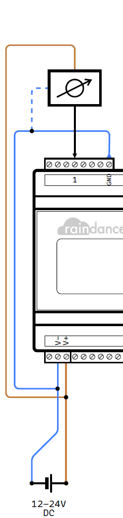
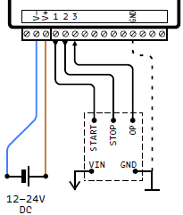
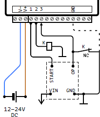
Typical connection of a control unit using a pulsed signal (active high, pulse width configurable) for Start (CH1) and Stop (CH2).
Feedback of the operational state via permanent signal (active high) via input CH3.
Create a common ground reference when using a separate power supply by connecting the GND terminal of the digital field.
|
||||||||
|
|
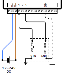
Typical connection of a control unit using a permanent signal (optionally configurable) on output
|
||||||||
|
|
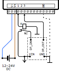
Example adaptation to a control unit using a permanent signal (active low) via a NC switch at CH1.
|
||||||||
|
|
Example adaptation for driving an NC switch to pull an active output low in order to stop the connected control.
The active output may be used as a feedback of the operational state.
Create a common ground reference when using a separate power supply by connecting the GND terminal of the digital field.
|
||||||||
|
|
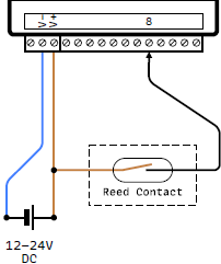
Typical connection of a counter at input CH8. The depicted example uses a simple Reed contact.
Alternatively, any kind of impulse generator can be connected to CH8 (input active high).
The impulse frequency has to be selected according to the desired application. |
Calibration of Analogue Inputs and Outputs
Ideally, there is a direct, linear connection between the value of an analogue input or output of the Beacon and the corresponding value range of the connected sensor or actuator defined in the pump settings.
Using the example of a simple 0-16 bar pressure sensor on an analogue input of the Beacon, 0 bar measured in voltage mode corresponds to a signal value of 0 volts, 16 bar to a signal value of 10 volts and the range in between is directly proportional (i.e. 2.5V = 4 bar, 5V = 8 bar, 7.5V = 12 bar, etc.).
In reality, however, there is often a deviation, very often not only by an invariable amount over the entire measuring range, but with different magnitudes at the two ends of the range to be measured. For this reason, it may be necessary to calibrate an input/output.
Calibration can be achieved by adjusting the value range on which the signal of an analogue input or output is interpreted accordingly.
Two measurements (with a multimeter, for example) at points as far apart as possible in the entire value range are required to adjust the value range to reality in a meaningful way.
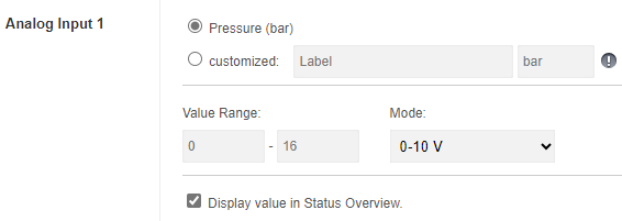
Example Pressure sensor 0-16 bar / 0-10 V:
Original setting in the portal:
Measurement of the transmitted values and corresponding sensor values:
|
|
|
|
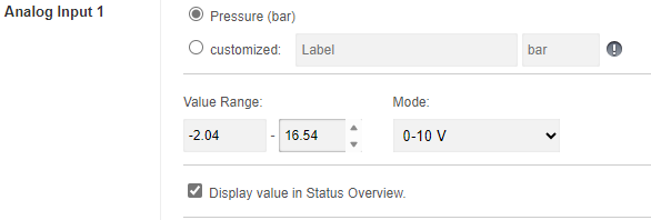
In the next step, these empirically determined values must be inserted into the following formula and calculated for each measured value of 0 and 10 volts:
Measured Value - Min. Measured Value.
Sensor Value = ————————————————————————————————————————————————————————————————————————————————— + Min. Sensor Value
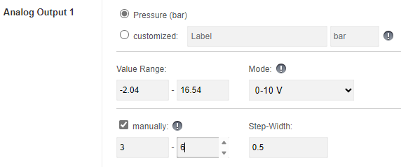
(Max. Measured Value - Min. Measured Value) × (Max. Sensor Value - Min. Sensor Value)The results of this calculation, from -2.04 bar for measured value = 0V or 16.64 bar for measured value = 10V, give the calibrated value range to be defined for the analogue input or output:
If this measurement/calibration relates to an analogue output, crooked (or simply nonsensical for the control system) values can be avoided in the manual selection by restricting the available value range using the new function. In the example case described, this would be 0 to 16 bar, alternatively further restricted to a range of 3 to 6 bar, for example, which can only actually be used:
Operation Mode »Mirror Image«
A combination of two or more Raindancer Beacons can optionally be used to reflect another device to be remotely monitored and controlled. Using this method, all signals coming from or going a Beacon will be available to a »Mirror« Beacon, via a »virtual cable extension«. Periphery connected to the »Mirror« (e.g. a PLC) can retrieve this information, process it and control the remotely
controlled device via commands sent from this »Mirror« to its actual counterpart.
The number of devices configured as »Mirror« are practically unlimited.
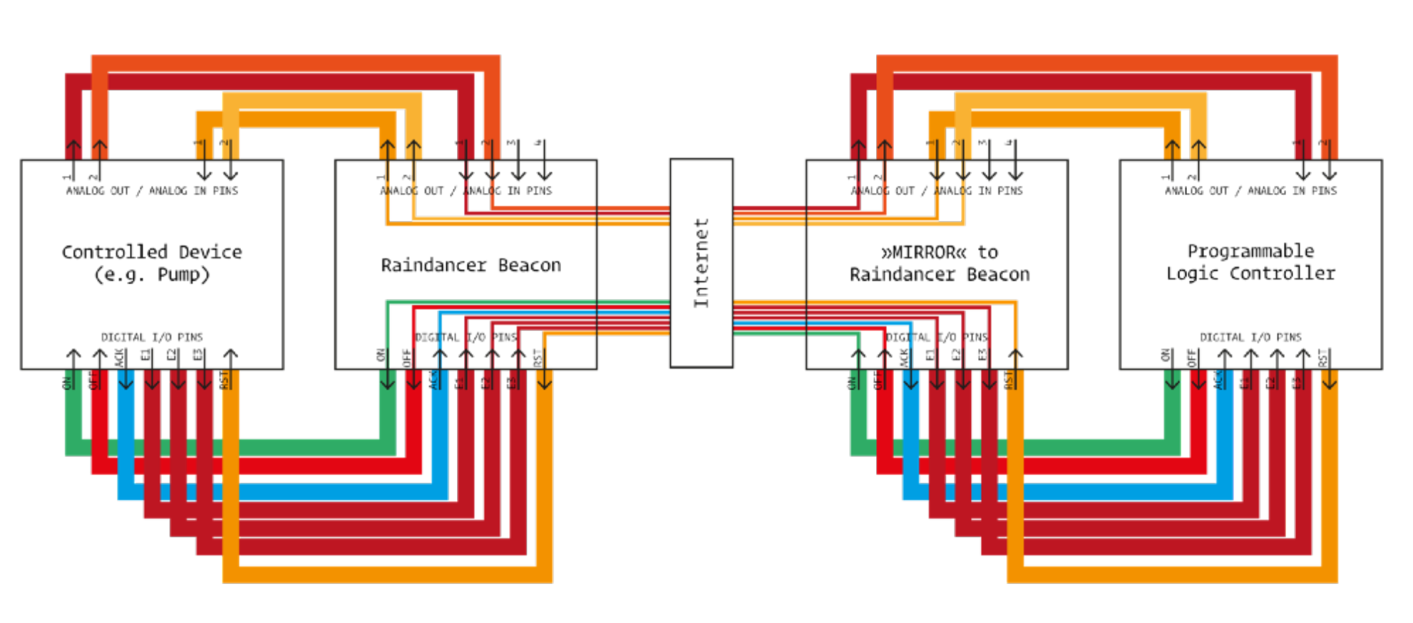
In order for a Beacon to be able to function as a »Mirror Image«, it has to undergo proper preparation, using a special configuration.